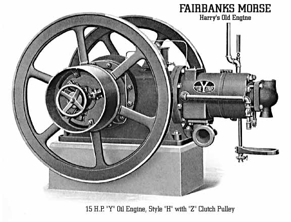
Fairbanks Morse "Y" Oil Engine - Style "H"
Fairbanks Morse Engine, General Electric Generator and Control Panel
This 4000 pound engine was built by Fairbanks Morse on January 8, 1920 and shipped out from their factory on February 7, 1920. The engine is a 15 horse power fuel injected Diesel and is water cooled from an external tank. The shelf below the head holds a vertical kerosene blow torch that heats a hot tube protruding from the combustion chamber for starting ignition. There is no need for wires, no spark plug, no points, no condensor, no battery, no switch, no valves and no gears. The exhaust port as shown above is the size of a 1# coffee can! It had many commercial applications including refrigeration, irrigation and oil line pumping, but this one produced electrical power to operate an induction motor driven line shaft as well as lighting in a machine shop. The General Electric generator and slate switch panel are shown on a separate page.
HOW IT WORKS:
These engines operate on a cycle which is completed by two strokes of the piston, or one revolution; commonly called the two-cycle system. They are designed to use kerosene, distillate, solar oil, gas oil, fuel oil and crude oil. They are not intended to operate on gasoline, and the system used differs from that of the ordinary two-cycle gasoline engine in several important particulars.
The main frame or crank case is closed, and serves as a pump for air. The air enters the crank case through an automatic suction valve, and as the piston moves toward the crank end, is slightly compressed. Just before the end of this stroke the exhaust ports in the bottom of the cylinder are uncovered, allowing the burned gases in the cylinder to escape to the exhaust.
Inlet ports in the top of the cylinder communicate with the crank case through the transfer passage. Shortly after the exhaust ports have opened these air ports are uncovered by the piston and pure air rushes from the crank case to the cylinder, cleaning the latter of exhaust or burned gases and charging it with fresh air. This air is trapped in the cylinder on the subsequent closing of the air and exhaust ports and as the piston moves toward the head end, compression of the charge of pure air takes place.
At approximately the time when the head end dead center is reached, the injection pump, located on the side of the cylinder, forces a fine spray of oil fuel into the spherical combustion chamber in the cylinder head. This spray of oil vaporizes and mixes with the compressed air in the combustion space. At the dead center when the compression has reached its maximum, ignition automatically occurs. The following rise in pressure drives the piston forward resulting in useful work. After expansion has occurred the exhaust ports again open, and the cycle of operations is completed.
Here is the start-up and run of a 10 horsepower unit by Chuck Moss in Hawaii...
Chuck Moss explains the refurbished 1931 engine that kept the Aina na Hoku Kai coffee farm supplied with electricity.
INSTALLATION:
The foundation should be prepared in accordance with the drawing furnished with each engine. This drawing gives the location of driving belts, exhaust pipe, and all out-side dimensions. A sufficient space, of at least two feet, should be allowed on all sides for easy access by the attendant.
If the engine must be located where the air is dusty or not clean, it can be equipped with a connection by which the air can be piped from a cleaner place. This special fitting is not regularly furnished with the engine.
The instructions on the foundation drawings sent with each engine are to be carefully and precisely followed with reference to the exhaust piping. These instructions are the result of careful and exhaustive study of the action of the exhaust of a two-cycle engine and should be followed exactly to obtain the best fuel consumption and the highest power capacity. If any departure seems necessary, the advice of the factory should be obtained.
When the exhaust is to be carried further than 12 feet, or when more than one elbow is used, the size of pipe should be increased.
The foundation being prepared, with the bolts firmly embedded and projecting the proper distance, the engine is to be set over them and leveled with four wedges. A thin grout of cement and sand should be poured over the top of the foundation, a dam of wet sand around the engine base serving to retain the grout. When the grout is thoroughly set, the nuts on the foundation bolts may be tightened. Extreme care must be taken to keep the engine level on the foundation.
The exhaust pot must be installed so that no strain is put on the pipe connecting the pot with the engine. Large bolt holes are provided in the flange connecting this pipe to the pot, so it can always be ascertained whether the pot is set too low by taking out the cap screws holding up this flange, and when the pot is low it should be raised by putting sheet metal pieces under it.
If greater silencing is required than is given by the exhaust pot sent with the engine a concrete pit can be installed in the ground adjacent to the engine, but in that case the advice of the factory should be obtained on the location and construction of the pit.
The usual arrangement for cooling with running water is shown by chart 1476GN2. The water supply pipe 1 is to be connected to the tee 2. which is shipped attached to the engine. The cock 3 is provided to regulate the supply of cooling water to the cylinder jacket. The outlet from this jacket is at the top of the cylinder bead as shown, the connection 4, with tee 5, and thermometer 6, being regularly furnished with the engine. This thermometer indicates the temperature of the main jacket outlet. Its location should not be changed. The overflow pipe 7 is to be connected to the tee 5, and so arranged that the outlet water can flow freely through it without restriction. All "pockets" or "traps" in the piping must be avoided. The cock 8 is provided to regulate the supply of water to the jacket of the combustion chamber cap. The outlet from this cap jacket is to be connected at 9, and must be arranged for a free flow without pockets or taps. This outlet pipe 9, must not be connected to outlet pipe 7 in any case, but must be entirely separate. It is very desirable that the overflow at the end of this pipe 9 be visible, so that it can be told at a glance whether or not any water is being passed through the combustion cap jacket. At 10 and 10 unions are to be provided for convenience in removing the combustion cap. At 11 a cock is provided for a drain for the combustion cap jacket, and at 12 a plug or drain cock must be arranged, by means of which all of the piping can be drained. A cock 13 is provided for draining the cylinder jacket. All water should always be drained off, after each run of the engine, when there is even the remotest danger of frost, otherwise a frozen or cracked cylinder or pipes may result.
 When a single water tank, or a tank with cooling tower is used for cooling, with centrifugal pump for circulation, the connections should be made according to Chart 1475GN2. In this case the suction 1 of the centrifugal pump is connected to the bottom of the cooling tank, and the discharge pipe 2 is carried horizontally along the side of the engine foundation to the head end of the engine, where it is to be connected to the tee 3 at the engine just as described above for running water. The overflow pipes must be kept separate and are to be carried over the top of the cooling tank and allowed to discharge separately and freely into the tank. The ends of the pipe 4 must not be allowed to extend below the surface of the water in the tank. The same drain connections as for running water must be made at the engine, and the suction pipe should also be fitted with a tee 5 and a plug for drain.
The fuel tank may be located outside of the building in a covered pit, as shown, and should be placed in a horizontal position and enough lower than the engine, so that the fuel will flow toward the tank from the engine. Any amount of fall from six to twenty-four inches will do. With this tank are furnished the proper connections for outlet and return pipe. Use the size pipe furnished. In connecting the fuel tank with the engine, care must be taken to wash out every piece of pipe or joint with gasoline or kerosene to remove all scale and loose matter, which, if left in the pipes, would interfere with the proper working of valves. Extra care must be taken in making all water and fuel pipe connections so that they do not leak; shellac should be used in the joints of fuel pipes and white lead in the joints of water pipes.
When an engine is installed in a basement, or in case the engine room floor is below the general level from which the fuel tank will be filled, care should be taken to have the top of the fuel tank slightly below the level of 'the engine room floor. In case the filling pipe connected to the fuel tank is extended to a point higher than the fuel reservoir on the engine, the fuel tank should be fitted with a reliable float device which will close the filling pipe before the tank is completely full. This float device will give warning so that the fuel will not overflow into the engine room in case there are any loose joints. Fuel tanks fitted with this float device will be furnished on special orders only.
Care should be taken to see that the cap on the fuel tank filler pipe is not screwed down so far as to cover the vent hole in the side of the filler pipe. If this vent is covered, the air cannot enter the tank and maintain atmospheric pressure on the fuel.
The suction pipe from the supply tank is to be connected to the bottom of the auxiliary fuel pump. The purpose of the cock in the fuel line is to restrict the supply of fuel slightly if the pump should deliver too freely to the glass reservoir on the engine.
The engine is shipped with a union attached to the lower end of the overflow pipe from the fuel reservoir, and to this union the return pipe is to be connected and carried down to the floor or through the floor as required and back to the fuel tank, with a gradual descent, to assist the free flow of surplus fuel back to the fuel tank.
Having all piping connected it will be well for the operator to familiarize himself with the following details: 
One essential feature of the engine, which, for best results, must always be in perfect mechanical order, is the injection pump, shown here. At the proper point in each revolution, the plunger of this pump is forced inward by the operating rod from the rocker arm, and in so doing it forces a small quantity of oil fuel into the combustion chamber through the injection nozzle. The length of the stroke of this plunger is controlled by the governor carried by the flywheel, and is automatically adjusted by it to meet the varying load. The suction valve is located below the pump body in the long bronze sleeve, and the discharge valve above the pump body. Each can be inspected or removed for cleaning by loosening the steel nut surrounding its sleeve.
It is essential that the stroke of the injection pump be correctly adjusted to provide easy starting, prevent the engine from overspeeding, and allow the engine to properly pull its full load. It may be adjusted by setting the pump plunger stop 99 or the operating rod 46, and the length of stroke can be observed by turning the engine over until the operating rod reaches the end of its travel through the stop 99. The distance from the end on the rod to the stop should be approximately 5/32" on the 25 H. P. size and 1/16" on the 10 H. P. size, with intermediate sizes in proportion.
When examining these valves, care must be taken that their small springs are not lost, and that all parts are clean when replaced, especially the valve seats. After examination, before the pump is re-assembled, it should be washed out thoroughly with gasoline or kerosene. Care should be taken not to damage the faces of the unions, otherwise they will leak under the pump pressure. Care should also be exercised when tightening the steel nut not to twist the sleeve to such an extent as to break the brazed joint between the pipe and the sleeve.
A supply of oil fuel is maintained in the auxiliary reservoir by the fuel supply pump on the side of the main frame. All excess fuel returns to the storage tank by the overflow located in the center of the reservoir.
The hand lever is used to operate the injection pump when starting.
The injection nozzle is fitted to a ground, tapered seat in the cylinder head, and held to its place by a collar nut. The nozzle tip is provided with a slot in one side to register with a dowel in the interior of the cylinder head, and when replacing the nozzle after examination, care must be taken that this slot fits exactly over the dowel and that the taper seat surfaces are clean.
The injection nozzle tip should be examined occasionally to see that the small hole in its end is open and clean. It can be cleaned with the needles furnished with the blow torch sent with the engine, but the hole must not be made larger.
The engine is equipped with a combustion chamber cap, held against the face of the cylinder head. When the engine is running this cap becomes sufficiently heated to maintain regular ignitions, but should not be allowed to become so hot as to glow brightly or to be clearly visible in the dark. This cap is also provided with a water jacket space which may be utilized for partial cooling of the cap if the engine is to operate on continuous heavy load, or if for any reason the cap should become too hot. The heat condition of the cap is largely dependent upon the characteristics of the fuel. If the cap is removed and replaced, the nuts should be drawn up evenly on the cover flange so the gasket does not leak. When replacing the cap on the cylinder head the starting tube should point downward to occupy the same position it did when the engine was received.
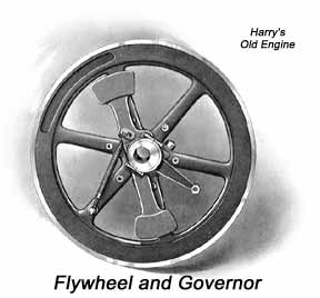
The governor is a simple weight, carried by the fly-wheel, on a single bearing. It carries an eccentric ring which actuates the injection pump through its operating rod. The throw of this eccentric changes with the position of the governor weight, due to changes in speed, and the amount of fuel is thus exactly gauged to suit the load carried by the engine. The centrifugal force is opposed by a single spring. The speed of the engine may be increased by tightening this spring, and decreased by the reverse.
The main bearings are of the ring oiling type. The oil reservoir of each of these bearings is to be kept properly filled with lubricating oil. For this purpose occasional observation should be made of the height of the oil in the gauge glass at each bearing. The upper limit of oil level is indicated by a white line around the gauge glass. The lower limit is given by the bottom of the glass. Oil must always be visible in it.
Occasionally, under continuous daily service, the oil should be drawn from the main bearing reservoirs and replaced with fresh, clean oil. Adjustment is necessary when excessive play in the bearings can be detected by applying a bar under the fly-wheel. Vibration of the fly-wheels when the engine is in operation, may also indicate a necessity for main bearing adjustment. This should be made in the following manner. First remove the bearing cap, then lift off the upper half of the bearing liner. This is a cast iron shell lined with babbitt metal. After removing this shell one or more of the thin metal shims between it and the lower shell may be removed from each side of the bearing, after which the top half of the bearing may be replaced and the cap again clamped down securely. End play can be adjusted with the paper shims between the bearing plates and the crank case. Neither adjustment should be brought up closer than with a play of 1/64", which can be felt when moving the parts in question with a bar. After adjustments have been made and the engine is put into operation, the parts adjusted should be watched for a time to note whether the running temperature grows excessive.
The main bearings may be completely renewed by first relieving the pressure of the crank shaft by means of a jack or bar under the fly-wheel, then proceeding as above, and in addition, rolling out the lower half of the bearing liner or shell in the manner which is self-evident on inspection. New liners which will interchange with those on the engines can be furnished from the factory, or the old ones can be rebabbitted.
The crank pin bearing is readily adjustable by loosening the nut on each connecting rod bolt about three-quarters of an inch, when the metal shims between the halves of the bearing may be removed from their dowels and replaced after removing one thin shim, or as many as necessary, from each side. It is not necessary to completely dismantle the rod. It is very important to properly replace the split cotter pins to prevent the nuts from loosening.
In a renewal of the crank pin bearing the new liners should be carefully fitted into the connecting rod and its cap, and the shim faces filed to the general surface. The liners should then be tried on the crank pin by hand to note whether they have sufficient end play (about 1/64") and whether they spot up evenly on the surface. In any case, after new crank pin liners have been fitted to an engine it is well to inspect them after running the engine for five or ten minutes at no load, and again after about a thirty minute run at a load. When the nuts are again drawn up, they should be set as tightly as possible with the socket wrench furnished. The cotter pins must always be inserted in the holes in the ends of the connecting rod bolts and the ends of the pins spread well apart.
The piston pin is hollow, of hardened steel and ground to exact size, and will wear very little. Its bearing is of special phosphor bronze. After long use, if necessary, it can be replaced by drilling out the bronze dowels in the bottom of the connecting rod and driving out the bushing, then inserting a new one furnished to exact dimensions. After the connecting rod and piston pin are replaced in the piston, care should be taken to see that the oil tube leading from the top of the piston extends well into the longitudinal boat on top of the connecting rod.
The engine is provided with a mechanical sight feed oiler forcing oil to the cylinder and to the crank pin bearing. No attention to the lubricating pump is required except to observe that it is always feeding properly, and to see that it has at all times a sufficient quantity of clean oil in the reservoir.
The lubricating oil should be run through a fine mesh wire strainer, inserted in a funnel, when the oiler is filled. The cover of the oiler should be in place at all times except only when the oiler is being filled. The oiler should be drained occasionally and washed out with gasoline or kerosene. The main bearing wells should also be washed out occasionally, and it will be wise to wipe out the crank case when opportunity offers.
The crank case drain must be kept open very slightly while running, as the pulsations of air assist in keeping it clear. It is very important not to allow oil to accumulate in the crank case.
HOW TO START "Y," TWO-CYCLE OIL ENGINES:
Before lighting the torch to start the engine, see that all the water jackets are completely filled. Is this is neglected, it will surely result in broken cylinder heads and combustion chambers.
Light the kerosene torch in the usual way, according to the instructions sent with it. While it is being generated the engine may be inspected and arranged to start.
See that the lubricating oil reservoir on top of the crank case is nearly full of. oil, using a good grade of high fire test gas engine cylinder oil.
In cold weather care must be taken that the oil is not so cold that it will not flow. This can be seen by cranking the oiler by hand and watching the discharge. If the oil is too cold, it must be warmed. Some oil flows at lower temperatures than others.
It is necessary to turn the crank of the oiler a number of revolutions to see that the oiler feeds properly, and to fill the lubricating pipes, which may have drained while the engine was shut down. See that the lubricating cup on the governor arm bearing is filled and in working order.
See that the auxiliary fuel reservoir is at least half full. If not, or as in the case of the first start, it can be filled and the fuel supply pump primed at the same time by pouring fuel directly into the reservoir, using the funnel and measure furnished with the engine. In the case of extremely cold weather, when using a very heavy fuel oil, this priming may be done with kerosene, which will shorten the time necessary to start. If water collects in this reservoir it should be drained away. A drain plug is supplied for this purpose and also for use in flushing the reservoir at times.
A screen is provided in the suction line to the injection pump as a safeguard against the entrance of dirt to the pump, and a similar one in the suction line of the auxiliary fuel pump. These screens should be kept clean. A good method is to remove the screen plugs and pour kerosene through them.
Work the injection pump two or three strokes by hand. With a little practice one can tell by the "feel" whether this pump is properly primed and its discharge pipe full of oil. If they are not, the union joints may be loosened and the oil worked through to the delivery pipe. This will seldom be necessary, except after having overhauled or cleaned out the pump and parts.
Observe the operation of the torch, adjusting it to give a hot blue flame. If the torch is set too close to the surface of the cap, a flame will project above the top opening of the cover. Mouth of burner should be set about 3" from starting tube.
Oil the rocker arm pins, and the pins of the governor carrying the governor spring.
The engine will be ready to start after about 8 to 10 minutes of heating the cap, and when the starting tube which projects from the cap shows red. At this time turn the fly-wheel until the piston is on the head end dead center, which can be told by the suction or discharge of air through the relief cock in the head. (In this position the key seat in the crank shaft will be straight up.) Give the injection pump two or three short strokes by hand, and turn the fly-wheel nearly one-half turn in the direction of rotation of the engine (engine runs over) with the relief cock open. Close the relief cock and then turn the fly-wheel sharply back against compression, being careful to grasp the proper arm of the fly-wheel so it can be released without danger to the operator when the explosion occurs.
The engine should then start in its proper direction. It may be advantageous to give one or two more strokes of the oil pump by hand, or in some cases to check the pump by hand, but the engine will automatically be giving the pump its maximum stroke, and if the pump is in order this will usually be sufficient.
A little experience in starting will soon prompt the operator as to the desired quantity of fuel to pump by hand. If the engine is flooded with fuel it will usually refuse to ignite, or will rock back and forth without completing a revolution. In that case the injection pump, to prevent introduction of more fuel, should be locked as when stopping the engine. The engine should then be turned over a few revolutions with the relief cock open to vent the excess fuel. To start an engine which has been running and is very hot all over will require a little judgment on the part of the operator in order not to flood it with fuel.
Make sure that the cylinder jacket is filled with water. Its flow may be temporarily restricted, or even stopped altogether, till the jacket becomes warm, but after that the outlet water thermometer should be the sole guide to the cooling. The thermometer should be so inserted in the outlet water jacket line that its bulb end is at all times submerged in water, and not in an air pocket.
If the load comes on the engine immediately after starting, the torch can be removed at the same time. Otherwise at light loads it should not be extinguished until the engine operates with quite regular ignitions.
TO STOP THE ENGINE:
Draw back the injection pump lever slowly-not suddenly, and lock it in position with the pin hanging from the chain. While the engine is coasting to a stop, turn the crank handle of the oiler a few revolutions so that the piston and cylinder will be nicely bathed in oil for the period the engine is standing idle.
Drain all jackets and pipes if there is the remotest possibility of freezing weather. It does not pay to take any chances.
WHEN THE ENGINE IS IN OPERATION:
The amount of oil to feed from the force feed oiler will, of course, depend upon the size of the engine and its operating conditions. For the 10 H. P. engine about 25 drops per minute on the cylinder and about 10 drops per minute on the crank pin will be a reasonable amount, and for the 25 H. P. engine about 60 drops per minute on the cylinder and about 20 drops on the crank pin. Intermediate sizes would be in proportion. On all sizes about one drop per minute on the governor eccentric will be sufficient.
An excessive amount of lubricating oil on the cylinder results in abnormal formation of carbon which deposits in the exhaust ports, or may even pass through and accumulate as a liquid in the exhaust pot.
It will frequently be found best to use no water in the jacket of the combustion chamber cap, excepting at heavy loads, but in case the cap shows red, no matter what the load is, water should be used to keep the temperature down. Water will seldom be needed at light loads as the engine will run much better under this condition without water. If the engine has been operating at a considerable load, with water in the cap jacket, and the load is then reduced to a point where normally no water is needed in the cap jacket, it is well to drain it to obtain the best operation at the light load.
When carrying any load, the explosions should be perfectly regular, and the strokes of the injection pump plunger should be evenly graduated. If this is not the case, the governor may be sticking, due to neglect of lubrication of its bearing.
Irregular operation can also be caused by a sticking of the check valves in the injection pump or in the injection nozzle, due to oil with f oreign impurities which have not been properly screened out. This has been mentioned before.
MISCELLANEOUS INSTRUCTIONS:
If the engine runs with irregular ignitions on light loads when using a light grade fuel, inspection should be made of the combustion chamber cap and injection nozzle tip. The cap is fitted with an internally projecting tube. The largest part of the oil from the nozzle tip should enter this tube when injection occurs. This can be tested by holding the cap against the cylinder head and giving the fuel injection pump a sharp stroke with the hand lever. The spray must enter the tube in order to get the best light load operation.
Do not confuse the external (nickel) starting tube with the internally projecting (iron) ignition tube. The ignition tube is needed particularly for securing good operation on light loads with kerosene and other light oils. On some heavy oils a deposit of carbon will take place in the tube and in such cases the engine will be found to operate well at all loads with this tube entirely removed.
These tubes have pipe threads and can generally be removed by a pipe wrench. When only a stub is left, a tapered chisel or part of a file can be driven inside and the tube unscrewed with a wrench.
The injection nozzle tip should occasionally be examined, and the spray hole in its end cleaned by means of the cleaning needles. The tip should be washed carefully with kerosene or gasoline before it is replaced, and it is absolutely necessary that the tip be screwed tight to its seat against the end of the nozzle body, otherwise there will be leakage of fuel, and irregular operation.
 To take out the injection nozzle and tip, first remove the injection pipe 65, then the collar nut 67 which holds the injection nozzle in place; turn this collar nut over and slip it back over the injection nozzle with the threads pointing out, and place the connection nut 96 which was removed from the injection nozzle, back on the nozzle, and screw up tight against the collar nut, thus using the connection nut as a jack to withdraw the nozzle.
When replacing the injection nozzle in the cylinder head, special care must be taken that the groove in the nozzle tip is placed fairly over the dowel in the cylinder head. If this point is not observed, the nozzle tip and dowel will both be ruined, and the engine will not operate properly. If the ground joint faces on the injection pipe connections are injured in any way, leakage will result, and proper operation cannot be secured.
If, after the engine has been in use for some time, it seems to lag in power capacity, or has a tendency to "pound" at full load, an inspection should be made of the cylinder and the exhaust ports, by removing the cylinder head. The hand hole plate on the exhaust elbow beneath the cylinder will be of assistance in examining the condition of the exhaust ports. The piston and rings can be seen through the opening covered by the plate on the top of the cylinder. When using a heavy grade of fuel it may be necessary to clean the ports of bridging carbon formation from time to time. Carbon is not likely to form in the exhaust pipe or pot.
When a loss of compression is noticed, the piston should be inspected. The piston can easily be removed by taking off the cylinder head and disconnecting the connecting rod bolts at the crank pin end. This gives complete access to all interior parts of the engine. The piston rings are of cast iron, and should remain free in their grooves. Any accumulation of carbon from the lubricating oil which tends to stick the rings should be washed out with kerosene; otherwise the rings are not to be changed or adjusted in any way till necessary to replace them. If the rings have been allowed to stick fast, the compression and explosion will blow past them, and the combustion will be poor, due to poor compression.
When a new engine is subjected to a heavy continuous load, it is well to take out the piston after a few days and examine it and the cylinder. If the bridges between the ports are very bright, showing hard bearing, they should be scraped down to prevent cutting.
The oil fuel, when put into the storage fuel tank, should be poured through a screen to remove dirt of all kinds. This will assist the small screen in the fuel reservoir at the engine. The fuel must at all times be kept warm enough for pumping.
If the valves of the injection pump become leaky, they should be very carefully ground into their respective seats with the use of a fine grade of carborundum paste, flour of glass, or pumice stone, but not with emery, as even the finest grades of this are too coarse.
Leaky valves allow the fuel to "dribble" into the combustion. space during the wrong portion of the cycle. This usually causes prefiring or knocking.
A governor in which the weight sticks on the pin in the fly-wheel hub will race or give poor regulation and operation. It is due to neglect of lubrication of the pin. The governor weight will have to be removed from the pin, cleaned, oiled and replaced. To do this, the fly-wheel hub clamp bolt should be removed, an iron wedge driven into the slot, the key removed and the fly-wheel moved back enough to allow the governor weight to be removed from the pin.
It is well to examine the governor pin quite frequently by removing the collar on the end of the pin and sliding the governor weight partly off the pin.
If the fuel passages in any part of the injection pump device become obstructed, the governor weight cannot overcome the resistance, but will clatter against the stop on the fly-wheel arm.
If the injection pump receives only one stroke in a number of revolutions of the engine, the friction drag on the top of the governor weight should be inspected. This drag consists of a plunger in the large end of the governor weight, held out by a spring against a hardened steel plate fastened to the fly-wheel arm. This plunger should work freely.
 The air suction valve at the front end of the crank case consists of a leather flap against a flat seat. If, in starting the engine, the air blows back through this valve from the crank case, the leather should be inspected. Absolute refusal of an engine to start may be due to lack of air, caused by trouble in this air valve. The leather valve must cover the seat at all places. If it is found out of place, so the seat is not completely covered, it must be readjusted. If the leather has softened so as to be forced into the openings of the seat, it should be renewed.
The leather air suction valve should not have a lift of more than 5/16". Where it is found to be more than this amount, it should be reduced by cutting off the guard over the valve, reducing the lift at the outside edge to 5/16" on the larger sizes and 1/4' on the smaller sizes.
An inspection of the tightness of the bolts, nuts and parts in the enclosed crank case is recommended to be made once a week. This can be easily done without removing any parts except the air suction valve plate and fittings.
