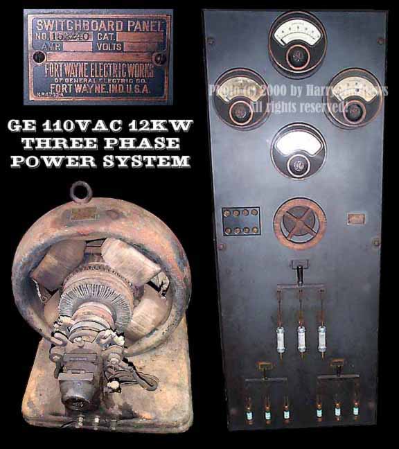
The above photo: Copyright © 2000 by Harry Matthews.
This system produced electrical power to operate an induction motor driven line shaft as well as lighting in a machine shop. It was belted to a 15 HP Fairbanks Morse Oil Engine.
The above photo: ALTERNATING CURRENT MACHINERY by William Esty 1912 Page 153.
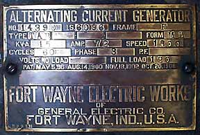
GENERAL ELECTRIC THREE-PHASE ALTERNATOR
The above view shows the 12 kilowatt 120 volt three-phase revolving-armature type of alternator built by the General Electric Company for use in small isolated plants. The alternator is belt-driven at 1,800 r. p. m. and, therefore, requires four poles to give a frequency of 60 cycles.
The view also shows three collector rings mounted on the armature shaft for the collection of the three-phase currents, and a commutator between the rings and the armature core. The special feature of this machine is that it requires no separate exciter, for the armature is wound with two distinct windings, one of which is connected to the commutator and supplies the exciting current to the field coils. The main armature winding generates the three-phase alternating currents and is connected to the three collector rings. The field structure consists of laminated pole pieces cast into a rigid stationary frame. The field-magnet cores are wound with coils which furnish a magnetic flux which is common to both alternator and exciter armature windings.
 These machines are built in three sizes and rated at 7.5, 15, and 25 kw. at unity power factor, and at 6, 12, and 20 kw., respectively, at 0.8 power factor. Standard voltages are 120, 240, 480, and 600 volts at 60 cycles, and their ratings are based on either two or three-phase operation. For single-phase operation any one of the phases may be used, but the rating then is only 70 per cent of the polyphase rating on account of the heating.
The above from: ALTERNATING CURRENT MACHINERY by William Esty 1912 Page 153.
The above from: HAWKINS ELECTRICAL GUIDE #4 1917 Page 1,203.
MATERIALS USED FOR SWITCH PANELS
There are various materials used for switchboard panels, namely, slate, steel, and marble. These have been referred to as Titanic era equipment, as envisioned in a mad scientist lab with bare-metal, "touch this and you die" knife switches. It takes a hydraulic crane to lift my switch panel!
Slate is a natural product obtained from quarries. To be suitable for switchboard work slate must be carefully selected for insulating qualities as well as for strength, and when it is used in its natural color must be selected for appearance as well. It has greater mechanical strength than marble, but inferior insulating qualities. The three varieties of the finished switchboard product used are: natural black slate, dull black marine finished slate, and black enameled slate.
Natural Black Slate consists of slate, in its natural color, which is rubbed with oil to bring out a rich, black appearance. It is not easily soiled and needs only an occasional application of oil to keep it in first class condition. Natural slate is suitable for use as an insulating medium up to and including 1200 volts, alternating or direct current.
Dull Black Marine Finished Slate consists of slate to which is applied a dull black lacquer, giving an appearance closely resembling natural black slate. The slate itself, before being lacquered, may not have a uniform color. The finish is very durable, although not so good as the natural black slate. The mechanical strength is equal to that of the natural black slate, but the marine finished slate is not recommended as an insulating medium for more than 550 volts, direct current, or 440 volts, alternating current. This material is no longer used by the Company, except where specified or to match existing installations.
Black Enamel Slate consists of slate finished with black japan baked and rubbed down to a highly polished surface. On account of the polish it is easily marred, and reflects light into the operator's eyes. This material is no longer used by the Company except where specified or to match existing installations.
Steel: A high grade of furniture steel is used extensively for switchboard panels where strength and durability a given prime consideration. Suitable insulation is provided for the current carrying parts.
Marble: There are several varieties of marble suitable for switchboard work, the most serviceable being Blue Vermont, Pink Tennessee, Gray Tennessee, and Domestic White Italian marble. Marble can be used as an insulating medium for potentials up to and including 3500 volts. Panels of marble are polished on the front and on exposed edges, then varnished on the other edges and on the back. Marble panels can be supplied, if desired, with a dull black finish. A black enamel finish could also be applied, but the process of enamelling the marble makes it brittle, rendering it an undesirable material for switchboard use.
Blue Vermont Marble consists of marble in its natural color polished on front and edges. It is found in various shades and markings. It has better insulating qualities than slate, but has not as great strength, and should not be used where it would be subject to heavy jars. It absorbs oil and grease, making it very difficult to keep in first class condition. It is also difficult to match existing panels when ordering additions. It is the practice of the Company to use this material only where specified or to match existing installations.
Tennessee Marble can be obtained in either pink or gray shades. It also absorbs oil and grease, although it is not quite so easily disfigured as the lighter colored marbles.
Domestic White Italian Marble comes from the Rutland, Vermont, quarries. It closely resembles foreign marble, and has the same general characteristics.
The above from: GENERAL ELECTRIC COMPANY 1925 CATALOGUE 6001B Page 196.
SWITCHBOARD INSTRUMENTS TYPE R-6 ALTERNATING
AND DIRECT-CURRENT THOMSON ROUND PATTERN
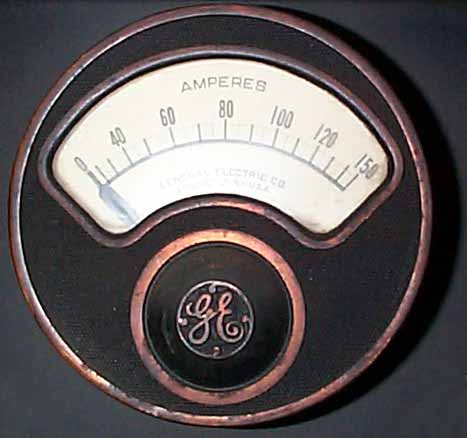
Type R-6 voltmeters and ammeters
have been developed to meet the demand for a compact, accurate and moderate line of instruments for use on alternating and direct-current switchboards.Type R-6 instruments are constructed on the well-known Thompson inclined coil principle and embody the same high grade construction which characterizes the various instruments'of this type.
The design and manufacture have received the most careful consideration, with the result that a mechanism has been produced
which will maintain a high degree of accuracy under the most severe operating conditions.
The moving elements are extremely simple and light in weight, and are mounted on highly polished pivots suspended in sapphire jewels. Friction is thus reduced to a minimum and the possibility of injury to the jewels and pivots is rendered very remote.
Type R-6 instruments give a maximum torque or directive force. This, in combination with the light moving elements, enables the pointer to take up a definite position with each change of current, and insures accuracy over long periods of service.
A permanent and reliable controlling or restraining force, one of the essentials of continued accuracy, is effected by the use of a high grade phosphor bronze spring.
Type R-6 instruments are highly dead beat. This important quality allows quick and accurate reading, and also protects the pointer and moving element from inJury due to violent load fluctuations.
This method of damping is very effective, introduces no friction, and is free from the objectionable features common to many liquid or air damping systems.
The Type R-6 instruments are contained in cast iron cases and in addition the measuring element is surrounded by a shield of laminated soft iron. The instruments can thus be placed close to one another without danger of mutual interference, a feature of the highest importance on crowded switchboards.
The scales are very satisfactory as to length, legibility and distribution. The various calibration points are carefully determined by comparison with our laboratory standard, which insures accuracy throughout the range.
Each instrument has the word "Amperes" or "Volts" printed conspicuously on the scale, enabling one to identify an ammeter or voltmeter at a glance.
Type R-6 instruments are made in the back-connected form and are provided with connection studs, which also serve to secure the instruments to the switchboard.
The standard finish is dull black.
Type R-6 ammeters are made self-contained up to and including 600 amperes. Instruments up to 100 amperes can be used on all voltages up to 2300. It is recommended, however, that 5-ampere instruments and current transformers be used on all circuits above 750 volts.
Current transformers are not included in the list prices, the price of a standard current transformer should be added to the price of a 5-ampere instrument when current transformers are necessary.
Type R-6 voltmeters are made in capacities up to and including 750 volts, and can be used in connection with potential transformers on alternating-current circuits of any higher voltage. When ordered with potential transformers the scales are marked in secondary volts, unless the order calls for marking in primary volts. When instruments are intended for use with transformers, the frequency of the circuit must always be given in order that the proper transformers may be supplied.
Instruments up to and including 175 volts are self-contained. Instruments above 175 volts have an external resistance box secured in a cage suitable for mounting on the back of the switchboard.
All voltmeters are equipped with a movable volt marker operated by a small screw beneath the monogram on the dome.
The above from: GENERAL ELECTRIC COMPANY 1925 CATALOGUE 6001B Page 694.
CR8000 AND CR8001 D-C FIELD RHEOSTATS
FOR FRONT AND BACK OF PANEL MOUNTING
GENERAL: In the construction of CR8000 and CR8001 field rheostats, the resistance coils are embedded and held in place in a special cement, which is a particularly good conductor and electric insulator. As shown in the illustration the contact buttons are circular and are spaced a sufficient distance apart to prevent dirt, dust from accumulating and short circuiting them.
In order to conform to the present standard switchboard practice, that is of having instruments and fittings on the front of the board of a black finish, the standard handwheels supplied with these rheostats are of a highly polished black material, thereby adding greatly to the appearance of the rheostats, as well as furnishing a pleasing effect when mounted on the switchboard panel.
A polished brass handwheel can be supplied with rheostats using 10-in., 12-in. and 15-in. plates if desired. In order to facilitate the drilling of switchboard panels on which these rheostats are to be mounted, diagrams showing drilling dimensions are furnished with each rheostat. Drilling templates will be furnished upon request.
RESISTOR: The resistance material used in CR8000 and CR8001 field rheostats is an alloy which has a negligible temperature coefficient, and which will not disintegrate under constant use. Hence the rheostats maintain constant resistance when in service. The 6-in. plates have 24 divisions of resistance, the 10-in. plates have 35 divisions of resistance, the 12-in. plates have 50 divisions of resistance, and the 15-in. plates have 70 divisions of resistance. The advantages obtained by having a large number of divisions of resistance are evident, that is, the operator can maintain a very even generator voltage or accurately adjust the speed of motors when the rheostats are used for these purposes.
The above from: GENERAL ELECTRIC COMPANY 1925 CATALOGUE 6001B Page 958.
TYPE LP-1 LEVER SWITCHES
BACK CONNECTED FOR MOUNTING ON I-, 1 1/4,- 1 1/2- OR 2-IN. PANELS
DOUBLE BLADE-ROUND STUDS-SATIN FINISH
125 AND 250 VOLTS, D-C. OR A-C., 500 VOLTS, A-C.
The Type LP-1 lever switches are back connected. They have current-carrying parts of highest grade copper (98 per cent conductivity) with satin finish. All contact surfaces are accurately machined. Switches are listed without fuses and with connections for N.E.C. fuses.
Switches without fuse connections are rated: 125 volts d-c. or a-c.; 250 volts d-c. or a-c. (can be used up to 275 volts d-c.); 500 volts a-c.
Switches with N.E.C. fuse connections on hinge are rated: 250 volts d-c. or a-c.; 500 volts a-c.
Straight handles are used on all single-, double- and triple-pole switches.
The above from: GENERAL ELECTRIC COMPANY 1925 CATALOGUE 6001B Page 547.
SQUIRREL CAGE INDUCTION MOTOR
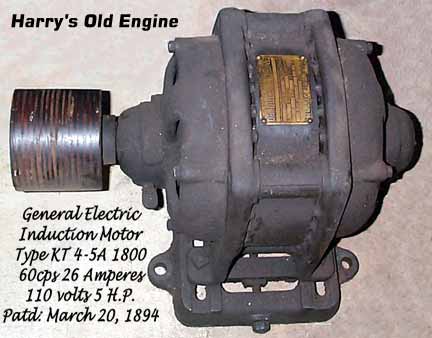
Induction Motor Type KT 4-5A 1800 Form C
Cycles 60 H.P. 5 Amperes 26 Volts 110
Speed No Load 1800
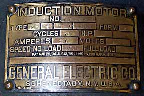
Patented March 20, 1894 August 13, 1895 June 25, 1901 March 14, 1905
The qualities essential to satisfactory operation have been obtained in General Electric Company's polyphase motors by careful attention to all details of design, material, manufacture and inspection. End shields are designed to give close clearances at shaft openings, at which grease seals are used to prevent dust entering the oil reservoirs.
The STATOR combines strength and compactness with rigidity and low weight per horse power. Wide and well braced feet are cast integrally with the end frames.
A - Ventilating openings in end frames are in a vertical plane, securing efficient ventilation and protecting windings against dirt and dust.
B - Stator laminations are directly exposed to the air, allowing effective and natural radiation of heat.
C- G-E moulded insulation provides mechanical protection to well insulated field windings and enables motor to operate successfully in installations where it is exposed to magnetic or abrasive dust, weak acid or alkali fumes, or moisture.
Ventilation is provided by means of fan blades cast integrally with the end rings. The ventilation secured is equally effective
for either direction of rotation.
The illustration shows a cross section of the rotor bars. The complete rotor forms a perfect one
piece casting, free from blowholes or other imperfections.
The use of the cast rotor overcomes inherent difficulties and weaknesses of other methods of connecting end rings to rotor bars.
In the G-E cast rotor construction the end rings and bars are integral, being cast in one operation, thus insuring a durable and well-balanced rotating member of great rigidity. The elimination of the usual mechanical method of joining bars and end rings, used in
other forms of small squirrel-cage rotors, insures long life and freedom from operating troubles.
BASE: The sliding base permits, floor, wall or ceiling, suspension. Forward or reverse movement by means of a single adjusting screw (D). Heavy holding down bolts (A) give rigid motor support. Milled grooving (B) to assure driving alignment. Guide washers (C) to prevent "slewing."
Paper pulleys used on practically all G-E belted motors have superior belt tractive surface, combined with lightness, durability and accurate balance.
The above from: GENERAL ELECTRIC COMPANY 1925 CATALOGUE 6001B Page 746.
Two-phase vs. Three-phase.
Due to the superior distribution of the stator windings, three-phase motors are slightly more efficient at all loads than two-phase motors of corresponding size. The power-factor is also higher especially at light loads and the starting torque with full load current is greater. Furthermore, for equal conditions of load and voltage, the amount of copper required in the distributing system is less. Consequently, whenever service conditions will permit, three-phase motors are preferable to two phase.
The rotor of the Form K motor has a short circuited winding of the well known squirrel cage type which, owing to the absence of external connections, is particularly simple and substantial. As there is no possibility of sparking caused by moving contacts the Form K is especially suitable for operation in powder mills, gas plants, etc where sparkless operation is absolutely csscntial.
The above from: General Electric Company Power and Mining Dept. Bulletin #41505 Nov. 1916.
Don't forget to look in on my BELTS and PULLEYS page for old factory line shafts!
