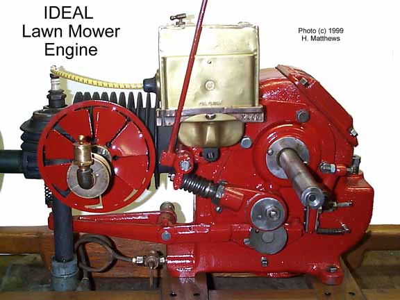
Ideal (hit 'n miss) Lawn Mower Engine 3/4hp with 11 inch Flywheels
This engine is from the Ideal Power Lawn Mower Company of Lansing, Michigan.
The Model R #3270 22 inch cut Estate Mower with WICO Magneto. Patented April 8, 1913 on the block fuel tank soft plug.
RESTORATION NOTES:
Never run an engine of unknown condition! You don't know where it's been or what may be inside.
The cam bolt was loose and could have come in contact with the crank.
The bolt holding the governor latch was sheared off inside its tapped hole.
Both nuts on the rod bearing cap were completely loose and had no pins.
The piston crown was stamped 3270 and the cylinder flange was stamped 3270, but someone had installed 3250 rings! Not good for compression!
This is a small engine and probably would have damaged only itself, but a large engine failure of these types can be catastrophic. Even rolling over a large engine before a complete check out can bust rocker arms, destroy fuel pumps or bend linkages. The best way is to do a complete teardown and put it back together in KNOWN condition.
The cam shaft assembly is bolted to the cam gear through the governor side main bearing hub. This bolt should be completely tight so as to prevent the bolt from ever sliding back into the works. :-(
When removing the governor latch assembly, first open the crank case lid and using an open end wrench, remove the lock nut from its mounting bolt.
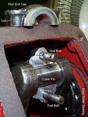
The rod bearing cap took 4 shims between each end of the shell. These are just over .004 each, made from an aluminum soda can, although most shim stock mentioned on the net is made from more potent beverage than my type-II nutrasweet laced caffeine laden refrigerated canned swill. At least the aluminum is thin enough to easily cut with heavy scissors and it does the job well.
The ROD and the CAP are marked with a DOT on one side of each. Be sure the dots are on the SAME side when you replace the cap. I note that this rod is drilled with an oil hole on the top and the bottom, but the wrist pin bearing is slotted on one side, which should be up. The wrist pin also has a hole at its center and when the mounting bolt is in place, this will determine whether that hole is up or down. Both sides of the piston have three holes from the oil ring to drip (spatter) oil onto the wrist pin. The long and short of all this is that you should make notes of all these things when you take something apart. In this case, I think the engine has been apart so many times that everything has been previously replaced in confusion.
The crank shaft roller bearings on this engine are adjusted by the thickness of the gasket material that is used under the hubs. If the gaskets are too thin or missing, the bearings will have too much end load and will over heat. Just a slight amount of end play will allow it to turn over with extremely low friction.
The last restorer installed what appears to be six 1/8" rings, two each in the three 1/4" ring grooves. Lots of drag and very little compression. There are also ring expanders under the two lower grooves. I'm thinking that I'll simply replace them back to original equipment. The cylinder diameter is 3.283 on a Starret of unknown calibration and the piston ring grooves are 0.0254" using grouped feeler strips and a micrometer, the top groove being a somewhat looser than the others.
The WICO magneto is extremely stingy with spark output. Having the luxury of a few spares, I have tried out several on it and have come to the same conclusion with each. This after a fresh recharge, a capacitor test and observation of points adjustment. The WICO simply has to trip fast or it'll have weak output. My hottest engine spark is in the Jaeger with the Type 2 drive, a much better design with a hair trigger and a fast return spring. The drive on this engine is a modified Type 1 with the return spring assembly INSIDE the trip spring assembly. These drive types are discussed in the Magneto page.
I FOUND THE PROBLEM!!! The main drive spring on the Type 1 assembly over time had become compressed. This is a VERY heavy spring, but nonetheless, it needed stretching out a bit. With my largest screwdriver and the bench vise, one by one I spread out the coils ever so slightly. The overall result was to make the spring about an 1/8 to 1/4 inch longer. This spring builds up pressure on the trip release lever until the fixed surface of the trip arm comes up into contact. At this point, the magnets give in and the main spring gives the armature one Hell of a quick throw down 1/4 of an inch. IT WORKED! I now have a really neat spark at the plug and as soon as I get the new rings, this old iron will be ready to RUN!
OPERATING INSTRUCTIONS
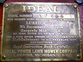
Before starting the engine, remove the hand hole cover and put in the crankcase one-quarter pint of Gargoyle Mobile "B", Polarine Extra Heavy, or oil of similar body. Then fill the sight feed oiler on the cylinder and adjust to drop from six to eight drops per minute. Inspect the spark plug and set the points about one thirty-second inch apart, or the thickness of a worn (silver) dime.
TO START ENGINE WITH HIT AND MISS TYPE OF GOVERNOR
First. Set the spark control lever of the magneto in the straight up and down position. This retards the spark for starting.
Second. Open the needle valve in the carburetor one and one-quarter turns and hold up on the air valve located on the under side of the carburetor until gasoline drips from the carburetor.
Third. Place starting crank on the crank shaft, turn engine to compression, then give a quick jerk upward. Repeat until explosion occurs. Do not attempt to spin the engine. It is both dangerous and unnecessary.
Fourth. As soon as the engine starts, move the spark control lever forward to the notch nearest the cylinder. This advances the spark for running.
Fifth. After the engine starts, close the carburetor needle valve gradually until correct mixture is obtained and engine is running smoothly. Be sure that the sight feed oiler is always open when the engine is running, and closed when engine is stopped.
TO STOP ENGINE
Place spark lever in notch farthest from cylinder. With engine stopped, be sure that the gasoline is shut off and the sight feed oiler closed.
LUBRICATION
The main engine (roller) bearings are lubricated by the splash system from the oil reservoir in the crank case. If directions for starting have been followed, your crank case is properly filled with the necessary quantity of oil to supply the splash to the mail bearings.
The sight feed oiler on the cylinder should be adjusted to drop from six to eight drops per minute. This will supply sufficient oil to lubricate the piston and cylinder with a surplus running into the crank case to maintain the proper oil level. The oil should be drained from the crank case occasionally to free it from dirt. A shut-off cock is provided for draining, which is located on the underside of the crank case. There is also a shut-off cock on the side of the crank case for determining the proper oil level.
There are cup grease connections on the fan shaft, idler pulley and exhaust lever, which should have daily attention when in operation. All bearings oiled with the pressure system use a light grade of cup grease or hard oil. The governor weight and the governor speeder latch holder should be oiled occasionally with machine oil.
CONNECTING ROD
Examine the connecting rod bearings often and do not let them run too loosely. However, in taking these bearings up, do not get them so tight they will run hot. Use enough bearing liners to permit drawing the bolts absolutely tight.
CARBURETOR
The function of the carburetor is to vaporize the fuel and mix it with air before it enters the cylinder. The amount of fuel needed to form a perfect mixture with the air is regulated by the carburetor needle valve.
HIT AND MISS GOVERNOR
The revolutions of the flywheel to which the governor weight is attached tend to throw the governor weight out from the hub of the flywheel, causing it to come in contact with the cap screw located on the top of the governor speeder lever and press it out. This pushes the governor latch (marked D) forward until it catches in the latch block (marked E) located on the end of the walking beam. This holds the exhaust valve open and cuts out the fuel until the speed decreases slightly when the latch unhooks, admitting fuel just often enough to maintain the desired speed.
To adjust the latch (D), turn the engine until the cam (C) has forced the cam roller (B) to its lowest point. Then set the latch so there is about 1/32" of clearance between the latch (D) and the latch block (E). Less clearance will cause irregularity of speed, and more clearance will allow the cam to hit the cam roller hard and make considerable noise.
TO CHANGE THE SPEED
To increase the speed, tighten tension on the governor weight spring located on the fly wheel. To decrease the speed, loosen tension on the governor weight spring.
DO NOT try to adjust speed by turning the cap screw on the top end of the Governor Speeder Latch Holder.
TIMING THE VALVES
Any engine must be correctly timed to develop its power and operate properly.
To time the valves, first see that the crank shaft and the exhaust cam (C) are set in proper position as shown above. Next, loosen the locking nut on the valve stem adjusting screw and turn the adjusting screw up or down as needed until it just touches the exhaust valve stem. Then tighten the locking nut so as to securely lock the adjustment. Test this adjustment by turning the fly wheel back and then turning it forward, noting the exact point that the exhaust valve starts to open. The valve should start to lift when the crank shaft is 35 degrees ahead of bottom dead center.
If for any reason the engine has been dis-assembled and gears removed, they must be replaced so the exhaust cam is in its proper position to open the exhaust valve when the crank shaft is 35 degrees above dead center. Otherwise it will not be possible to time the valves properly.
TIMING THE SPARK
To time the magneto, set the advance & retard lever in the center notch. Then turn the crank shaft so that the key (A) is on dead center on compression as shown. Then loosen nut (B) and turn the connection (C) until the arm (D) trips. Then tighten the nut (B) to lock.
THE SPARK PLUG SHOULD BE CLEANED OCCASIONALLY
Clean spark plug of all carbon deposit or soot by washing in gasoline and wiping or brushing off with a small brush, or by boiling in a solution of lye and water. Plugs may be tested by connecting wire to a plug and laying body of plug on some part of the engine. Turn engine slowly and see that the spark occurs at the points of the plug, not up in the body of the plug. If spark does not take place at points, clean plug thoroughly and examine carefully for cracks in the porcelain.
If no spark is produced, see that the armature (100) returns and makes firm contact with the cores (107) after being tripped off. Failure to do so indicates friction of moving parts or lack of oil. Turn the flywheel over slowly until the armature is tripped from the cores. If the armature does not snap quickly away, or does not open 3/32" to 1/8", it indicates binding, friction due to lack of oil, or a broken drive spring.
CLICK HERE to see the old mower in the rough on Paul Maples page.
Go to the Magneto Page for more Wico information.
Here's a recent YouTube movie by a Smokstak poster:
This page is provided as a public service, but it is supported by your purchases
at our Old Engine bookstore. Please check it out.
Quilters: check out my wife's Quilting Books.
Or, buy videos, games, toys and books for the kids at BookMouse.com
There's a WHOLE LOT more to this site so click and cruise around!

 CLICK HERE