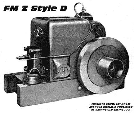
Fairbanks Morse "Z" Engine Style "D" 1-1/2 H.P.GENERAL1. Foundation - The engine skids are drilled for four 3/8" bolts. If the engine is to be located on a permanent
foundation, follow the foundation plans which will be furnished free on request. Leave sufficient space around
the engine so that all parts will be accessible. 2. Exhaust - For an outdoor installation, no exhaust pipe need be used. For an indoor installation, remove
the muffler plate and install a 1" pipe. This pipe should be as straight as possible and not exceed 40'. It is
recommended that the lowest part of the exhaust line be fitted with a 1" x 6" pipe nipple projecting downward
and having a stop cock at the end to drain condensation which otherwise might enter the engine. This is especially
advisable with a long exhaust pipe. 3. Auxiliary Pulley - When installing a pulley on the pulley shaft, see that all burrs are removed from the end of
the shaft and the bore of the pulley, and do not drive the pulley on the shaft. The bore of the pulley and the diameter
of the shaft are machined so that the pulley can be pushed on, and tightened in place with the set screw. 4. Fuel-This engine will operate on gasoline only. 5. Rated Speed - Flywheel pulley 1500 R. P. M. Pulley shaft 750 R. P. M. OPERATING INSTRUCTIONS6. Before Starting the Engine - (a) Remove the oil gauge rod and plug in the crankcase cover and pour in approximately
one quart of engine lubricating oil (Medium for summer, Light for winter). Replace the gauge plug and rod. The oil should
register at the "FULL" mark on the rod. Do not fill above this mark. (b) Fill the fuel tank with gasoline (approx. 3 quarts).
(c) Fill the water hopper (approx. 2 gallons). Hot water will assist starting in cold weather. 7. Starting the Engine - Open throttle valve approximately ONE turn. Place starting crank in end of crankshaft on
flywheel side, and while closing the air inlet opening in the fuel mixer with the left hand, crank engine in a clockwise
direction. Do not close the air inlet for more than two revolutions. When the engine takes its first impulse, remove the
starting crank. Read paragraph 16. 8. After the Engine is Running - (a) Adjust throttle valve to best running condition. (b) After first start tighten cylinder
head nuts when engine has warmed up. (c) Replenish water in hopper as required. (d) Check the oil level at intervals as
determined by experience, and replenish when the level is below the mark on the gauge rod. Note: - The engine must be
stopped and the oil gauge rod screwed tightly in place when the oil level is checked. 9. Stopping the Engine - (a) Close the throttle valve. (b) In freezing weather precaution must be taken to prevent breakage
due to the freezing of the cooling water. It is strongly recommended to drain the water from the engine by means of the drain
plug in cylinder head. SERVICE INSTRUCTIONS10. Lubricating Oil - Drain crankcase after every 100 hours of running and refill with new oil. A plug is provided in the
end of the crankcase for draining. See paragraph 6 (a) for instructions on refilling, and paragraph 8 (d) for instructions on
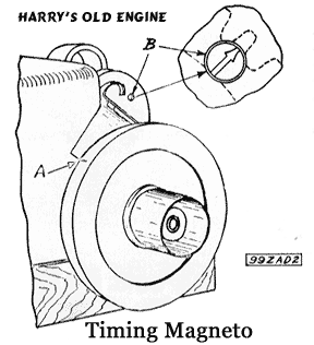
checking the oil level. 11. Timing Magneto - When replacing the crankcase cover, care must be taken to mesh the magneto gear properly.
Proceed as follows: Turn flywheel until piston is moving toward cylinder head on compression stroke to a position where
the mark on the rim of the flywheel lines up with the joint between the cylinder base casting and the crank case cover. See A on
diagram 99ZAD2. Remove the pipe plug from crankcase cover at the side of the magneto gear and turn the gear so that
the mark on the gear comes in front of the inspection opening. See B on diagram 99ZAD2. Then drop cover in place,
making sure that marks do not move from position. Note: The speed regulator lever must be shifted to a position nearest
the flywheel when the cover is dropped in place. 12. Setting Gear Train - The proper relation between the crankshaft and camshaft is obtained by meshing the two beveled
teeth on the camshaft gear and the one beveled tooth on the crankshaft gear. 13. Adjusting Bearings - The main bearing caps, camshaft bearing caps, and connecting rod cap are to be filed for
adjustment. Do not file the connecting rod shims. 14. Checking and Adjusting Valve Clearance - Remove the crankcase cover (16B) Then measure the valve clearance on
low cam. The clearance should be .005" to .007". If necessary to adjust the clearance, remove the camshaft and withdraw the
valve tappets (3841). Take out the disc (3844) and the shims (1881A) and (1881B) from the tappet and adjust the shims to
give the proper clearance. Shim (1881A) is .031" thick, and shims (1881B) are .003" thick. When replacing the shim and
the disc in the tappet be sure to insert the shim first, as the hard steel disc must bear against the end of the valve stem.
Check the clearance after the camshaft has been replaced, and be sure that the gears are meshed properly. (See paragraph 12.) 15. Setting Butterfly Valve - Remove the crankcase cover. Then force governor weights out to their extreme position, allow
them to drop back slightly (about 1/32" at end of weight), and wedge them in this position. The lever on the butterfly valve
should then be down as far as possible. Adjust the governor control shaft lever if necessary. 16. Fuel Check Valve - Occasionally remove the fuel check valve at the lower end of the suction tube to permit cleaning
the screen and removal of any foreign matter from the ball and seat. Gum from some gasolines may be deposited on the ball.
Should the engine stand idle for some time the drying gum may cause the ball to stick with resultant starting difficulties. 17. Removing Scale or Deposit - To remove scale or deposit in the cylinder head and water jacket, drain the engine and fill
with a solution of one part commercial hydrochloric (Muriatic) acid to ten parts water. Allow to stand over night, and then
wash out with fresh water. Disclaimer! 18. Magneto Replacement - External parts for the magneto will be furnished as shown in the repair parts list. If
replacements are necessary on internal parts, avoid breaking the seal and return the magneto complete to the nearest
company representative. 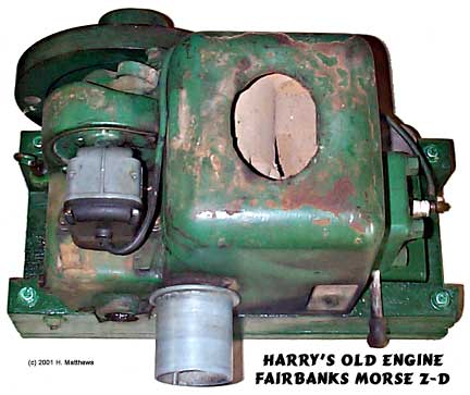 CLICK HERE for Fairbanks Morse manuals and catalogs.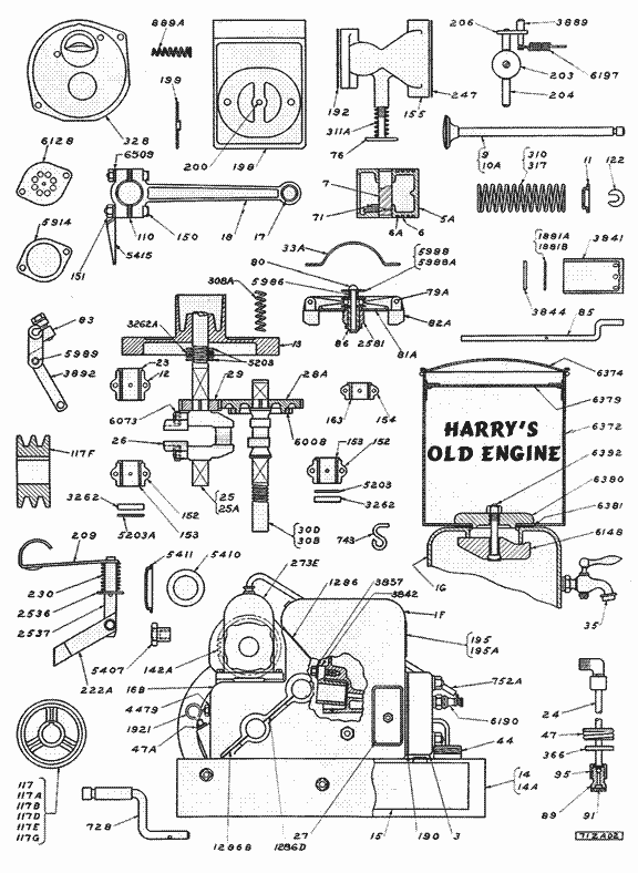 Courtesy Fairbanks Morse and Company, Chicago 1935. |
Please visit our sponsors on the Business Card Page
This page is provided as a public service, but it is supported by your purchases
at our Old Engine bookstore. Please check it out.
There's a WHOLE LOT more to this site so click and cruise around!
![]()
| ENGINES | SHOWS | SEARCH | SUPPLIERS | IGNITIONS | ABRASIVES | CLASSIFIEDS | BOOKS |
SCRAM back to Harry's Page!
Page!
![]()
Published by Harry F. Matthews © 1995, 2001. ALL RIGHTS RESERVED!