LINE SHAFT PULLEYS and BELTING
(CONTINUED)
POWER TRANSMISSION BY BELT
|
16. The Effective Pull. In Fig. 11, let d and f be two pulleys connected by a belt, d being the driver and f the follower. To avoid undue slipping, the belt must be drawn
Suppose the two pulleys to be stationary and that the belt is put on with a certain tension; then, T1 will be equal to T2. If, now, the pulley d is turned in the direction of the arrow, it tends to stretch the lower part of ihe belt, increasing its'tension still more, while the tension of the upper part is diminished. This goes on until the difference of the tensions is sufficient to start pulley f. The difference (T1 - T2) between the tensions in the tight and loose sides of the belt is the force that does the work in transmitting power, and is called the effective pull. If S denotes the speed of a point on the belt, in feet per minute, which is practically the same as the speed of a point on the pulley circumference, the work done per minute is the product of the force (T1 - T2) and the distance S through which the point on the belt moves. Hence the work per minute = (T1 - T2) S foot-pounds. Now, 1 horsepower is the performance of 33,000 foot-pounds per minute; hence, if H is the horsepower transmitted, EXAMPLE 1. A pulley 4 feet in diameter is driven at 100 revolutions per minute, and transmits power to another pulley by means of a belt without slip; if the tension on the driving side of the belt is 400 pounds and on the slack side is 100 pounds, what is the horsepower transmitted? SOLUTION. S = 4 X 3.1416 x 100 = 1,256.6 ft. per min. From the formula, EXAMPLE 2. The diameter of the driving pulley is 36 Inches; It takes 150 revolutions per minute and carries a belt transmitting 6 horsepower. What is the effective pull of the belt? SOLUTION. Speed of 'belt, in feet per minute, is (150 X 36 x 3.1416) / 12 = 1,413.7. 17. The Width of the Belt. A belt should be wide enough to bear safely and for a reasonable length of time the greatest tension that will be put on it; this will be the tension T1 of the driving side of the belt. As belts are usually laced, or fastened with metallic fasteners, both of which require holes to be punched in the ends, it is customary to use the breaking strength through the lace holes, divided by a suitable factor of safety, as the greatest allowable tension. The average breaking strength for single leather belts, through the lace holes, is 200 pounds per inch of width. This divided by 3, which is a suitable factor of safety for belting, gives 66 2/3 pounds. Thus, in the last example, the tension of the driving side of the belt was assumed to be 400 pounds. Hence using 66 2/3 pounds as the safe working stress per inch of width, a belt 400 /66 2/3 = 6 inches wide would be required. The tension T1, for any particular case, depends on three things - viz., the effective pull of the belt, the coefficient of friction between the belt and pulley, and the arc of contact of the belt on the smaller pulley. As the equations involving these quantities are somewhat complicated, Table I has been calculated. It will afford a convenient means for finding not only the width of belt for a given. horsepower, but the horsepower for a given width as well. In the first column, the arc covered by the belt is stated in degrees, and in the second column in fractional and decimal parts of the circumference covered., The third column gives the greatest allowable values of (T1 - T2), or the effective pull, per inch of width, for single leather belts. These values were computed by assuming a value for T1 of 66 2/3 pounds, and a coefficient of friction of .27. This latter has been found, by experiment, to be a fair value to use for leather belts running over cast iron pulleys, under conditions met with in practice. The arc of contact on the smaller pulley of a pair may be very readily found. Let R and r represent the radii of the large and small pulleys, respectively, and let h represent the distance between centers. Then, if the number of degrees in the are of contact is denoted by a, Cos a/2 = (R - r)/h. By substituting the known values of R, r, and h, the cosine of half the angle a is found, and the angle a/2 can easily be determined by referring to a table of cosines. This, multiplied by 2, will give the arc of contact, in degrees. EFFECTIVE PULL OF BELTS - Table 1
18. To use the table in finding the width of a single leather belt required for transmitting a given horsepower, the following rule may be applied: Rule. Compute the effective pull of the belt. Divide the result by the suitable effective pull per inch of width, as given in the third column of Table 1; the quotient will be the width, of belt required, in inches. EXAMPLE. What width of single belt is needed to transmit 20 horsepower with contact on the small pulley of 3/8 of the circumference and a speed of 1,500 feet per minute? SOLUTION. The effective pull is, from the formula In Art. 16, T1 - T2 = (33,000 X 20) / 1,500 = 440 lb. From Table I, the allowable pull per inch of width is 31.3 lb. Hence the width required is 440/31.3 = 14 in. Ans. 19. Horsepower Transmitted by a Belt. The process of finding the horsepower that a single belt will transmit must evidently be just the reverse of the preceding. It is, therefore, as follows: Rule. Multiply together a suitable value for the effective pull, taken from Table 1, the width of the belt, in inches, and the speed, in feet Per minute. The result divided by 33,000 gives the horsepower that the belt will transmit.
EXAMPLE. What horsepower will a 1 inch belt transmit with a speed of 900 feet per minute and an arc of contact of 180 degrees? SOLUTION. T1 - T2, from Table I, = 38.1. 38.1 X 1 X 900 = 34,290, which, divided by 33,000, gives 1.04 H. P., nearly. Ans. 20. General Rule for Belting. From the last example, it appears that a single belt traveling 900 feet Per minute will transmit 1 horsepower per inch of width when the arc of contact on the smaller pulley does not vary much from 180 degrees. This rule may be expressed algebraically as follows: (1) H = WS / 900 (2) W = (900 H) / S (3) S = (900 H) / W EXAMPLE 1. Two pulleys, 48 inches in diameter, are to be connected by a single. belt, and make 200 revolutions per minute; if 40 horsepower is to be transmitted, what must be the width of belt? SOLUTION. The belt speed is (200 X 48 X 3.1416) / 12 = 2,513 ft. per minute, about. EXAMPLE 2. What size pulleys should be used for a 4-inch belt that is to connect two shafts running at 400 revolutions per minute and transmit 14 horsepower? Both pulleys are to be of the same size. SOLUTION. By formula 3, S = (900 X 14) / 4 = 3,150 ft. per minute. Since this speed equals the circumference of the required pulley in feet X 400, the circumference of pulley is (3,150 x 12) / 400 = 94.5 in.; the diameter is 94.5 / 3.1416 = 30 in. Ans. 21. Double Belts. Double belts are made of two thicknesses of leather cemented together throughout their whole length; they are used where much power is to be transmitted. In Europe it is common practice to rivet as well as cement double belts. As the formulas for single belts are based on the strength through rivet or lace holes, when these are used, a double belt, if twice as thick, should be able to transmit twice as much power as a single belt; and, in fact, more than this, where, as is quite common, the ends of the belt are glued together instead of being laced. Double belts, however, are not usually twice as thick as single belts. Where double belts are used on small pulleys, the contact with the pulley face is less perfect than it would be if a single belt were used, owing to the greater rigidity of the double belts. More work, also, is required to bend the belt as it runs over the pulley than in the case of the thinner and more pliable belt, and the centrifugal force tending to throw the belt from the pulley also increases with the thickness. Moreover, in practice, it is seldom that a double belt is put on with twice the tension of a single belt. For these reasons, the width of a double belt required to transmit a given horsepower is generally assumed to be about seven tenths the width of a single belt to transmit the same power. On this basis, formulas 1 , 2, and 3 of Art. 20 become, for double belts, (1) H = W S / 630 (2) W = 630 H / S (3) S = 630 H / W EXAMPLES FOR PRACTICE1. If the effective pull on a belt per inch of width is 50 pounds, and the belt passes over a pulley 36 inches In diameter, which makes 160 revolutions per minute, how wide should the belt be to transmit 12 horsepower? Ans. 5 1/4 in. 2. What width of single belt should be used to transmit 5 horsepower when the belt speed is 2,000 feet per minute, and the arc of contact on the smaller pulley is 90 degrees? Ans. 3 1/2 + in. 3. Using the general rule, find the horsepower that a 16-inch single belt will transmit, the belt speed being 1,000 feet per minute. Ans. 17.8 H. P. 4. Using Table I, how much. power could the above belt be depended on to transmit if the arc of contact on the smaller pulley is
1/3 of the circumference? Ans. 14 H. P., nearly. 5. Required the diameters of pulleys necessary to enable a 10-Inch belt to transmit 9 horsepower at 125 revolutions per minute, both pulleys being of the same size. Ans. 2 ft., nearly. 6. How much power would the belt in example 3 transmit if the belt were double? Ans. 25.4 H. P., nearly. CARE AND USE OF BELTINGLeather belts are generally run with the hair or grain side next to the pulley. This side is harder and more liable to crack than the flesh side. By running it on the inside the tendency is to cramp or compress it as it passes over the pulley, while if it ran on the outside, the tendency would be for it to stretch and crack. Moreover, as the flesh side is the stronger side, the life of the belt will be longer if the wear comes on the weaker or grain side. The lower side of a belt should be the driving side, the slack side running from the top of the driving pulley. The sag of the belt will then tend, to increase the arc of contact, as illustrated by the full lines in Fig. 11. Long belts, running in any direction other than the vertical, work better than short ones, as their weight holds them more firmly to the pulleys. It is bad practice to use rosin to prevent slipping. It gums the belt, causes it to crack, and prevents slipping for only a short time. If a belt properly cared for persists in slipping, a wider belt or larger pulleys should be used, the latter to increase the belt speed. Belts, to be kept soft and pliable, should be oiled with castor or neat's-foot oil, or other suitable belt dressing, Mineral oils are not good for this purpose. Tightening or guide pulleys, whenever used to increase the length of contact between the belt and pulley or to tighten a belt, should be placed on the slack side, if possible. Thus placed, the extra friction of the guide pulley bearings and the wear and tear of the belt that would result from the greater tension of the driving side are avoided. 23. Guiding Belts.When a belt is to be shifted from one pulley to another, or must be guided to prevent running off the pulley, the fork or other device used for guiding should be close to the driven pulley, and so placed as to guide the advancing side of the belt.  This principle is sometimes made use of where pulleys have flanges to keep the belt from running off the pulleys. Where constructed with straight flanges, as in Fig. 12, if the belt has any inclination to run on one side, its tendency is to crowd up against the flange as shown at a, a. When constructed as in Fig. 13, however, with the flanges grooved as at c, c, the advancing side of the belt will be guided at b, just as it reaches the pulley, by contact with the thick portion of the flange, and during the rest of the way will not touch the flange at all. In Fig. 14 is shown the arrangement of a belt shifter; g is the driving pulley, and t and l are tight and loose pulleys on the driven shaft c d; b is the shifter, and can be moved parallel to c d. The acting surface, or face, of g is made straight to allow the belt to shift readily, and the faces of t and l are crowned - that is, the diameters of the pulleys are increased slightly toward the
centers of the pulley faces- so that the belt will not tend to run off. 24. The Climbing of Belts. In Fig. 15, suppose the shafts a, a to be parallel, and the pulley d to be cone-shaped. The right-hand side of the belt will be pulled ahead more rapidly than the left-hand side, because of the greater diameter and consequent greater speed of that part of the pulley. The belt will, therefore, leave its normal line at c, and climb to the high side of the pulley. This tendency is taken advantage of by crowning pulleys in the middle. Each side of the belt then tends to move toward the middle of the pulley; that is, the tendency is for the belt to stay on the pulley. 25. Belt Fastenings. There are many good methods of fastening the ends of belts together, but lacing is generally
used, as it is flexible like the belt itself, and runs noiselessly over the pulleys. Fig. 17 shows a method of lacing where double lace holes are used, b being the side to run next to the pulley. The lacing for the left side is begun at 1, and continues through 2, 3, 4, 5, 6, 7, 4, 5, etc. A 6-inch belt should have seven holes, four in the row nearest the end, and a 10-inch belt should have nine holes. The edge of the holes should be at least 3/4 inch from the sides, and the holes should not be nearer than I inch to the ends of the belt. The second row should be at least 1 3/4 inches from the end. Another method is to begin the lacing at one side instead of in the middle; this method will give the rows of lacing on the under side of the belt the same thickness all the way across. It is also quite common to cement the ends of a belt instead of lacing them together. To do this, the ends to be cemented are shaved off, with a uniform taper, for a distance about equal to the width of the belt, then coated with cement and laid together, and subjected to pressure until the joint is dry. BELT CONNECTIONS FOR NON-PARALLEL SHAFTS26. It very frequently happens that one shaft, must drive another at an angle with it. Sometimes this involves the use of guide pulleys, and occasionally guide pulleys must be used to connect parallel shafts, where the shafts are near together, or there is some obstruction in the way. In all such cases the point at which the center of the belt is delivered from each pulley must lie in the middle plane of the other pulley. The middle plane of a pulley is the plane through the center of the pulley, perpendicular to its axis. Unless the shafting is to turn backwards at times, it is immaterial in what direction a belt leaves a pulley; but it must always be delivered into the plane of the pulley toward which it is running. If it is necessary for a belt to run backwards as well as forwards, it must also leave in the plane of the pulley. This principle applies to the guide pulleys as well as to the main pulleys. 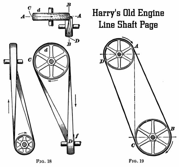 27. Shafts at Right Angles.The common method of connecting shafts at right angles is by means of a quarter-turn belt, as shown in Fig. 18. Here, the pulley d is the driver, rotating in the direction shown, and the pulley f is the follower. The point at which the belt is delivered from the pulley d lies in the middle plane of the pulley f, that is, in the line B B; also, the point at which the belt is delivered from the pulley f lies in the middle plane of the pulley d, or in the line A A. Thus arranged, the belt will run from d to f without running off either pulley. The reason for this will be made clearer by referring to Fig. 19, in which the belt is represented by A B and C D and is traveling in the direction of the arrows. The two shafts being parallel, and the pulleys lying in the same plane, the belt runs from A to B and from C to D with no tendency to run off. Let a line A C be drawn tangent to the pulleys at the middle points of their faces, where the belt leaves the pulleys. This line may then be considered as an axis around which the pulley B C may swing without affecting the. action of the belt. For, suppose the, pulley B C to be swung on the axis A C through a right angle, that is, into the position of pulley f, Fig. 18. Then, since the point A will still lie in the middle plane of B C, and the point C will still lie in the middle plane of A D, the action of the belt will remain unchanged; that is, the center of the belt at the point where it leaves either pulley will lie in the middle plane of the other pulley, and there will be no tendency to run off. If the pulley B C be turned through any other angle about A C, the required condition will be fulfilled and the belt will run properly. With the arrangement shown in Fig. 18, however, the pulleys cannot run backwards, because D, the point of delivery of f, is not in the middle plane A A, and C is not in the middle plane B B. The following simple method of locating the pulleys for a quarter-turn belt may be used in practice: Locate the pulley d and the machine so that the pulleys d and f will be as near the correct position as can be judged by the eye. Using a plumb-bob, drop a plumb-line from the center of the right-hand side of the pulley d, and move the machine until the, center of the back side of the pulley f touches the plumb line.
28. There is this objection to a quarter-turn belt: when the angle at which the belt is drawn off the pulleys is large, the belt is strained, especially at the edges and it does not hug the pulleys well. Small pulleys placed quite a distance apart, with narrow belts, give the best results, from which it follows that quarter-turn belts, like the foregoing, are not well suited to transmit much power. Fig. 20 shows how the arrangement can be improved by placing a guide pulley against the loose side of the belt. The driver d rotates counterclockwise, thus making A B the driving or tight side of the belt. To determine the position of the guide pulley, select some point in the line A B, as D; draw lines C D and E D; the middle plane of the guide pulley should then pass through the two lines. Looked at from a direction at right angles to pulley f, line C D coincides with A B; looking at right angles to pulley d, line E D coincides with A B.  29. A third method of connecting two shafts at right angles is shown in Fig. 21. In general, it is to be preferred to the quarter-turn belt. The pulley d is the driver. The belt passes around the loose pulley l and back around a loose pulley d' on the driving shaft behind d. It then goes around f, which is fast on the shaft a a, and finally back again and around d. Since the loose pulleys turn in a direction opposite that of their shafts, their hubs should be long. The two pulleys on each shaft must be of the same size. It is evident that either f or d can, be the driver and can run in either direction. It is to be observed that while a quarter-turn belt can be used with the shafts at an angle other than a right angle, the last arrangement cannot.  In Fig. 22 is shown a method of connecting the shafts when it is not possible to put the follower f directly under the driver d. The guide pulleys g,g' must be so placed that the belt will lead correctly from the point A into the middle plane of the guide pulley g', from B into the middle plane of d, and so on around. By twisting the belt at c, the same side will come in contact with all the pulleys; this is a desirable arrangement.  In the arrangement shown in Fig. 23, the shafts a and b would intersect, if long enough. Examples occur where shafts running on two sides of a room are to be connected, Guide pulleys g,g', like those in the figure, termed mule pulleys, are used. As their planes are horizontal, means must be provided to prevent the belt from running off at the bottom. Sometimes this is done by simply crowning the pulleys, and sometimes by putting flanges on the lower sides.  30. Other Examples of Belt Transmission. Guide pulleys are sometimes used to lengthen the belt between two shafts that are too close together to be connected directly, or it may be that it is not possible to get two pulleys in the same plane. Fig. 24 shows an arrangement of this kind. The diameter of each guide pulley should be equal to the distance between the planes of d and f. With the guide pulleys arranged as shown, the belt will run in either direction. It is more convenient, however, to place the guide pulleys on one shaft. In that case, their, axes will be on the line 0 0; g' will be in the line C K, and g in the line A B. Then the belt will be delivered from d into the middle plane of g'; and from g' into the middle plane of f. The belt will run in only one direction, however. A device for connecting two horizontal shafts making an angle with each other is given in Fig. 25. It can be used where a quarter-turn belt will not work successfully. The guide pulleys turn in the same direction, which is a convenience, because they can then be mounted on one shaft, turning in bearings at the ends, and the belt will run in either direction. The old meets the new and those who would preserve history. The foregoing treatise was written previous to 1906, the initial copyright having expired and the author anonymous. Much work and effort, however, was expended to convert this material into modern machine readable form. Please read it and enjoy it for your own immediate use only and refer to my copyright page before considering taking it for any other purpose. Your support of the Harry's Old Engine web site can be provided at P.O. Box 5612, Sarasota, FL 34277 or by your active interest in my book store and the many suppliers that sponsor my web sites. There are still a few places that have restored and operate this old equipment. One that we have visited is The Hanford Mills Museum in East Meredith, NY. For a look at some of the engines that powered this old equipment, have a look in The GALLERY. |
 tight. This will produce tensions in the upper and lower parts, which will be called T and T1, respectively.
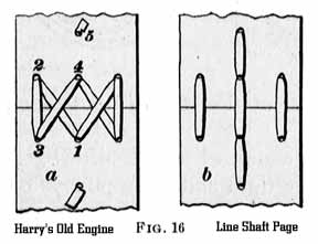 The ends to be laced should be cut squarely across, and the holes in each end for the lacings should be exactly opposite each other when the ends are brought together. Very narrow belts, or belts having only a small amount of power to transmit, usually have only one row of holes punched in each end, as in Fig. 16; a is the outside of the belt, and b the side running next to the pulley. The lace is drawn half way through one of the middle holes, from the under side, as at 1; the upper end is then passed through 2, under the belt, and up through 3,_back again through 2 and 3, through 4 and up through 5, where an incision is made in one side of the lace, forming a barb that will prevent the end from pulling through.
 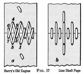 The other side of the belt is laced with the other end, first passing it up through 4. Unless the belt is very narrow, the lacing of both sides should be carried on at once.
 In case it should not convenient to move the machine, shift the pulleys instead. If it be desired to run the belt in the direction opposite to that indicated by the arrow in Fig. 18, shift the machine carrying f to the left until the center of the front side of the pulley f touches a plumb-line dropped from the center of the left-hand side of the pulley d; that is, from the point C.
SCRAM back to Harry's Page!
Page!
Reprinted by Harry Matthews © 2001, 2005. ALL RIGHTS RESERVED!