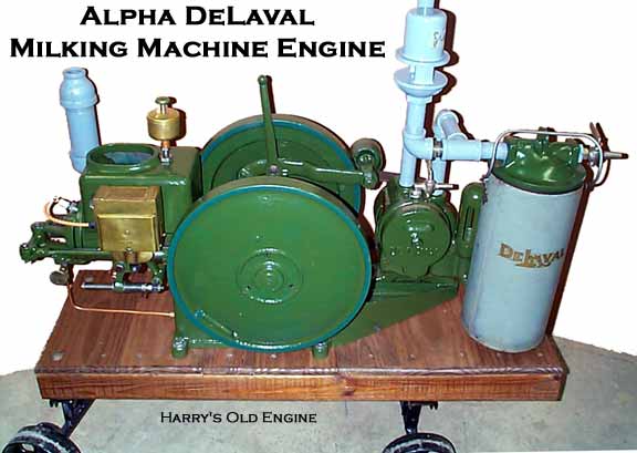
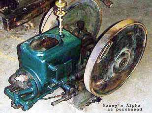
 Alpha Milking Machine Engine by Lauson My second engine find of '96 - an old hit and miss milking machine vacuum pump engine on the original heavy cast iron base. Thanks to Jim Fero of Wisconsin for the pump and idler assembly and the vacuum gauge.
See my DeLaval page for history, development, parts and operation of the De Laval Milkers that work off this Alpha pumping system. Instructions courtesy The De Laval Separator Company, November 1, 1925... GETTING ENGINE READY TO START1. Fill gasoline tank. 2. Adjust lubricator on cylinder to feed about 10 to 25 drops of oil per minute. Fill grease cups on main bearing, connecting rod bearings and camshaft bearings with cup grease. 3. Fill hopper of engine with water up to deflector plate. 4. Turn flywheels over slowly and note whether all parts work freely. Governor ball should be moved by hand so that it does
not stick. Also move exhaust valve by hand, by pushing against tappet lever. TO START GASOLINE ENGINES.
Turn retard handle (No. 330 Fig. 2) to the side so that it stands in a horizontal position. Open needle valve ('No. 173 Fig. 3)
so the mark on its rim is at top. Close air damper (No. 168 Fig. 3) by turning the handle to one side. Now with left hand on
handle of air damper and with right hand on handle in flywheel turn forward till engines starts. When engine has started
open air damper about half way and turn retard handle No. 330 straight down. After engine has run several minutes and is
thoroughly warmed up, open air damper as wide as possible by turning handle straight down. IMPORTANT. Be sure and turn retard handle No. 330 straight down for regular running. Never open needle valve
further than mark on its rim. Too much gasoline turned on at the needle valve results in too heavy a mixture and causes
fouling of spark plugs. CAUTION. When starting a new engine and same is in motion take an ordinary oil can and pour a little oil on end
of piston as it runs in and out of the cylinder. This assures proper lubrication of cylinder as it takes some time before oil
from lubricator is properly spread through the same. HOW TO STOP ENGINEStop engine by closing needle valve (No. 173 Fig. 3.) WHEN THE WATER BOILS IN THE HOPPER OF THE ENGINEWhen engine is running on a normal load it is perfectly natural that the water in the hopper of the engine should
come to a boil. Do not be alarmed about this, it will do no harm and engine will run correctly and efficiently with water boiling.
From time to time water lost by evaporation should be replaced. Keep enough water in hopper so that cylinder is always covered. THE CARBURETORGreat care should be taken that needle valve (No. 173 Fig. 3) on carburetor is correctly adjusted. Close it off as much
as possible. Watch the exhaust. Black or sooty looking exhaust indicates too much gasoline is coming in at the needle valve
and will cause fouling of spark plugs. Exhaust should be clear. Grey or bluish looking smoke from the exhaust indicates an
excess of lubricating oil. Always run engine with air damper (No. 168 Fig. 3) on carburetor wide open. CHECK VALVE No. 1004AFailure of check valve No. 1004A to function properly, causes engine to miss explosions, back fire and start hard. As a
remedy remove same and look for foreign matter in it. It should have a clear passage from tank to carburetor, but the ball
in same should close off passage when flow of gasoline is reversed. In case of doubt install new check valve. THE GOVERNOR The governor is of simple construction. To test its operation, turn flywheels forward until exhaust cam opens exhaust valve to its fullest extent. Then work governor by hand and note whether governor detent steel (No. 32 Fig. 4) can freely engage with governor toe No. 66. Normally there should be about 1-32' space between them. Examine end of toe and steel and if same are chipped or worn they can be reversed as they are double ended. If both ends of either steel or toe are badly worn they should be renewed. All parts of the governor should work freely. HOW TO ADJUST THE SPEED OF ENGINETo make engine run slower, screw down speeder screw (No. 153 Fig. 10) on governor detent. Normal speed of engine
is given on name plate. HEAD AND VALVESThe cylinder head should be removed occasionally and all carbon removed from end of piston and cylinder and face of
head. When head is off, the valves should be reground using a little emery and oil, powdered glass or a valve grinding
compound sold by nearly all garages. In replacing head be sure all surfaces are clean and draw all nuts up gradually,
not one at a time. TIMING GEARSThe timing gears are marked before engine leaves factory. If, for any reason cam-shaft and gear are removed, great care
should be taken to replace them properly in relation to each other. The mark on camshaft gear should be placed in contact
with the mark on small gear on crank shaft. The space between exhaust valve and tappet lever should never be more than
9-16" when roller is on lowest point of cam (See Fig. 4). Crankshaft should be in the position as shown on Fig. 5 when exhaust
begins to open and should be closed again when piston is back in the cylinder as far as it goes or in other words when the
engine is on rear dead center.  IGNITION INSTRUCTIONS - WICO MAGNETO EQUIPPED ENGINESThe Wico Magneto and its operating mechanism should be oiled every day the engine is run, with the same oil used
in the engine cylinder. There is little danger from excessive oiling. IN ALL IGNITION TROUBLES PUT FIRST ATTENTION ON SPARK PLUG. IN THE MAJORITY OF CASES THE PLUG IS FREQUENTLY THE CAUSE OF THE TROUBLE. CLEAN IT THOROUGHLY BY TAKING IT APART.
(SEE CUT AND INSTRUCTIONS BELOW). The construction of Wico Magnetos is such that they seldom go wrong and if trouble occurs the spark plug may be the
cause, having become fouled. HOW TO CLEAN SPARK PLUGS
In order to properly clean a plug its parts should be unscrewed. Carefully examine the inside insulation, which is the
part made of porcelain or mica. This part should be thoroughly cleaned, the best way being with a rag soaked in gasoline.
Never use paper or emery cloth, as this tends to roughen the porcelain or mica and thus invites a fresh coating of carbon.
If the carbon resists action of rubbing use a thin knife blade, to remove it. The distance between wires on sparking points
should be about 1-32", never more. (About the thickness of a thin worn dime). This distance between points should be closer
than is the general practice with automobile spark plugs. WHEN SPARK PLUGS FOUL FREQUENTLYFrequent fouling of plugs is caused by too rich a mixture. Close needle valve No. 173 on carburetor, as much as possible
(Fig. 3). This should be done when engine has become thoroughly warmed up, having air damper (Fig. 3) wide open. When
starting cold engine, air damper should be kept partly closed for a few minutes but open wide when engine is hot. Watch
the exhaust. Exhaust should be clear. Black or sooty exhaust indicates too rich a mixture, and will foul spark plugs. HOW TO TEST SPARK
If a magneto defect is suspected, test for sparking as follows: Remove wire from spark plug and hold end within
1/8" to 1/4" from any part of engine. Turn flywheels over slowly and when magneto trip lever (No. 325 Fig. 2) "snaps"
or trips a spark should occur at the end of wire, if magneto is in serviceable condition. If no spark, or only a light spark
occurs it may be due to sluggish action of magneto trip operating rod No. 331, due to it having become gummed up or
stuck with dirt or dust, or to lack of oil. To remedy this condition wash and clean off this rod and springs Nos. 335 and
336 with kerosene, and thoroughly oil the magneto and all parts of the operating mechanism. Operate push rod No. 29A
by hand and make sure that all parts work freely. Note whether return spring No. 336 brings back the trip lever No. 325
so that armature No. 100 makes a firm contact with cores No. 107 Fig. 7. HOW TO TEST POINT OF IGNITION AND HOW TO TIME Test point of ignition as follows: Turn lever No. 330 Fig. 2 in downward or running position. Turn flywheels over
slowly, holding intake valve open with left hand so compression won't interfere. Carefully watch magneto trip lever
No. 325 Fig. 2. When point of ignition has been reached you will note a distinct snap or trip of this lever in the direction
indicated by the arrow Fig. 2. When the trip or snap has taken place stop and note position of crankshaft. It should be as
shown on Fig. 8. This position is also indicated by an arrow on the flywheel rim Fig. 9. This arrow on flywheel rim should
be even or level with exhaust rod when magneto trips or snaps. Or in other words, when magneto trips or snaps flywheel
should be in the position as shown on Fig. 9. If not adjust trip operating rod No. 331 Fig. 2 until ignition is at correct point.
To get earlier ignition, loosen nut "A" and screw up nut No. 347 Fig. 2 thereby moving rod No. 331 in the direction indicated
by the arrow. To get later ignition adjust nuts in reverse order. LOSS OF POWERLoss of power may be caused by: IGNITION TOO LATE. The remedy is to adjust magneto trip operating rod No. 331
Fig. 2 so ignition is correct. See Timing Instructions above. EXHAUST PIPE INSTALLATIONThe exhaust pipe should be as short and free from elbows as possible. Exhaust pipes with elbows cause back pressure
and loss of power. However, if it becomes necessary to use one or more elbows it is necessary to use one size larger pipe for
every elbow used. This will avoid the detrimental effects of back pressure and loss of power. EXHAUST VALVE TIMING TOO LATEAdjust length of exhaust rod No. 29 so that there is 9-16' space between valve end and tappet lever, when roller of push
rod slide is on lowest point of cam. LEAKY VALVESTurn engine over slowly against compression and listen for a hissing noise at muffler and carburetor. Hissing noise
indicates leaky valves and valves should be reground. WORN CYLINDER AND PISTONSWorn cylinder and piston cause loss of power. This condition may easily be noted by gases and smoke blowing out of
end of cylinder when engine is running. When flywheels are revolved by hand there will be a hissing noise caused by gas
leakage. The only remedy is to regrind cylinder and have new piston and rings fitted. LEAKY VALVESTurn engine over slowly against compression and listen for a hissing noise at muffler and carburetor. Hissing noise
indicates leaky valves and valves should be reground. KNOCKING OR POUNDING ENGINESNever run a pounding or knocking engine but stop and locate the cause. Knocking if not remedied may eventually
cause broken crankshaft and completely wreck the engine. To take up crank bearings remove the nuts from crank box bolts
and remove one piece of shimming from each side of box. Replace box, tightly screw up bolts and try if too loose. If so, remove
more shimming until the proper adjustment is obtained. IMPORTANT. Never attempt to secure proper adjustment of any bearing by adjusting the nuts on bearing bolts. This
is dangerous and may wreck the engine as the nuts if not screwed down tightly are sure to work loose. Always have enough
shims between the halves of the bearings so that the bolts may be screwed down tightly, being sure to insert the cotter keys. CARBON IN CYLINDERExcessive carbon in cylinders is caused by running the engine with needle valve on carburetor opened too far.
(See carburetor). Carbon will cause pre-ignition and & noise similar to pounding called "pinging" by some engine men. In
such a case head should be removed and all carbon scraped from cylinder end of piston and face of head and incidentally valves reground. LUBRICATIONLubrication is most important. Care should be taken that all parts have been oiled and grease cups filled. Cylinder
lubrication should have special attention. Never run engine unless lubricator on cylinder has been filled and is working
properly. Use a good grade of gasoline engine oil. Pulso Pump Oil is recommended. HOW TO START KEROSENE ENGINESOpen gasoline needle valve painted red until mark is at top. Close air damper by raising handle to one side. Then start
same as for gasoline. Open air damper about half way after engine has started and wide open after engine has become warmed
up. After engine has run several minutes and become thoroughly warmed up open kerosene needle valve painted green so
mark is at top and close red gasoline valve. Before stopping always run engine on gasoline a few minutes as this will make starting easier. The 1-1/2 H.P. Kerosene engine has no air damper on carburetor. In order to start hold hand against end of carburetor
shutting off air supply until engine has started. EXPLANATION: Heads for 1-1/2 H.P. engines are of 3 types as follows:W4 - The first type is a head used in connection with the built in carburetor, the carburetor being a part of, or built into the head, and is used on 1-1/2 H.P. only. This type was discontinued but repairs can still be furnished. Carburetor parts are listed under built in carburetor group. W4A - This type is used on the 1-1/2 H.P. size carrying a separate carburetor (not built in as W4). It has been discontinued being replaced by W4B, which is same in all respects except that a spark plug hole has been added. W4A can not be furnished. W4B should be ordered in place of same as it will interchange. The user should in such a case screw a plug furnished into the old spark plug hole and place spark plug in head. W4B - Latest type head for 1-1/2 H.P. having spark plug hole in head. Order this for all Wico Equipped engines. Whenever W4A is wanted order W4B instead-it will interchange. WA & WB4A - This is the type used on 2-1/2 H.P. and 3-1/2 H.P. It has never been changed or altered. NOTE IMPORTANTAll engines numbered 40,000 or over are Wico Magneto equipped. All engines numbered 45,000 or over are equipped
with helical gears (teeth cut slanting) Flywheels are a Dress fit on crankshaft. In case of damage to some part necessitating removal of flywheel it is necessary
to send entire assembly to factory in order to have part replaced or order complete flywheel assembly.  The above text and drawings from Repair Parts Price List / Manual of Instructions Click on the following photos for more details... Pulso Pump Special Oil.Dismantled pump ready for cleanup.Pump inside shows moving vanes.The pulsator control disc.Bead blasted, pickled and ready for paint.Vacuum gauge.Pump brass tag.Engine piston assembly.Replacement pin and bushing made by Ed Deis.Cam and cam gear.Front view of finished engine.Also, see my Alpha VW vertical Lauson milker engine and the DeLaval page for history, development, parts and operation of the De Laval milkers that work off this Alpha pumping system. |
There's a WHOLE LOT more to this site so click and cruise around!
| ENGINES | SHOWS | SEARCH | SUPPLIERS | IGNITIONS | ABRASIVES | CLASSIFIEDS | BOOKS |
SCRAM back to Harry's Page!
Page!
![]()
Published by Harry F. Matthews © 1995 - 2000. ALL RIGHTS RESERVED!