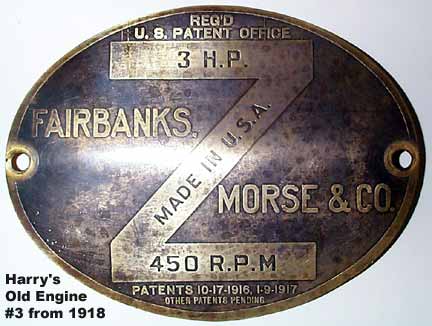
Harry's OLD ENGINE #3
Fairbanks Morse and Company 1918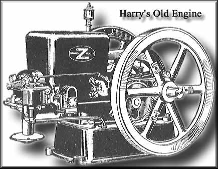 Before:  After: 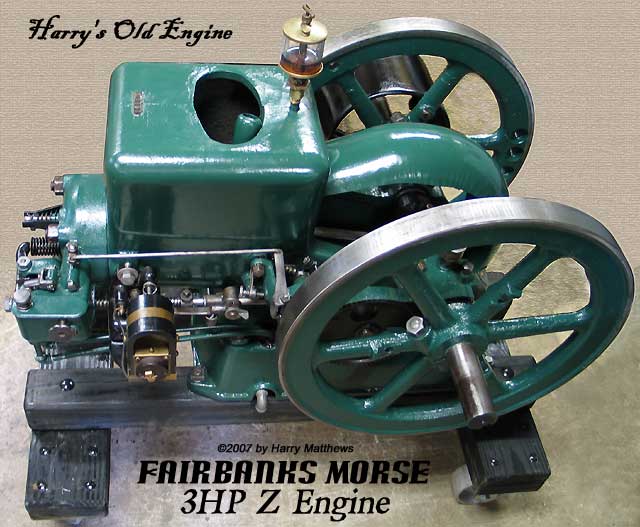 Fairbanks Morse 3 H.P. "Z" Kerosene EngineDistinctive Features of the "Z" Throttling Governor
|
| NOTICE: Starting cranks are a recipe for disaster. It is preferred to start these engines by manually turning the flywheels. How appropriate that what follows is step number 13. BE CAREFUL! |
13. Holding the suction or upper valve open with the left hand, with the starter crank spin the engine. After getting the engine in motion, release the suction valve and half close the air inlet opening in bottom of reservoir with fingers of left hand for one revolution only, and then remove fingers while still continuing to crank. If held longer too much fuel will be drawn in. The mixture will not ignite if there is too much fuel in it, and the fuel must be forced out by cranking.
AFTER ENGINE IS STARTED
14. After the engine takes its first impulse remove the starter crank. The igniter should be set on running position with the mark E up - this is the point of early ignition. The throttle should be again adjusted to give as little fuel as the engine will run on. After the engine is running nicely adjust the throttle valve. The position at final test on distillate was with the mark straight down, but it should be adjusted to give as little fuel as the engine will run on. The position varies with the fuel and the temperature.
15. The engine will usually run on oil fuel after using one reservoir full of gasoline. When the engine is warm enough to run on oil fuel the fuel pump should be thrown into action by throwing out the lock-out lever.
16. The water throttle valve on the cylinder head should not be opened except to quiet hard explosions which may be noticed when engine is on heavy continuous load, and only enough to serve the purpose. This valve must be closed a few minutes before stopping engine so that the interior of the cylinder will be dry. The water spray valve is on 6 H. P. engines only.
17. Fill water hopper two-thirds full and replenish this water as it evaporates. It is expected to boil away.
TO STOP ENGINE
18. To stop engine, first close water throttle valve, then close throttle To Stop. Then close cylinder oiler (527), and in freezing weather, drain out the water.
DESCRIPTION OF ENGINE PARTS AND ADJUSTMENTS
19. The cam gear (28) is marked with two center punch marks on face of tooth. The pinion (29) on the crank shaft has one tooth with two center punch marks. This tooth should come between the two marked ones on the large gear. If the engine is taken apart and the marks on the gears cannot be found, or if the gears are replaced, the engine should be timed as follows. Place the crank (25A) in a vertical position and pointing up. Then set the cam gear with the nose of the cam straight up. Next see that there is about 1/16' clearance between the end of the exhaust rod and the adjusting screw in the valve rocker arm. Such a setting should bring the valve timing very nearly as described in paragraph 20 below.
20. The cam should begin to open the exhaust valve 30 degrees to 35 degrees before outer dead center. The cam should close the exhaust valve when the crank is about 5 degrees above the inner dead center. The valve can be turned with the fingers the instant it is lifted from its seat.
21. While operating engine the hopper should not be filled more than three-fourths full of water, otherwise water will splash out more or less when it boils. The water should never be allowed to fall as low as the top of the cylinder wall, as the cylinder will then get too hot. It is to be expected that the water will boil under heavy load and the engine will work properly when the water is boiling. Put in more water as it evaporates.
22. The engine jacket is liable to be broken by freezing if water is left in during cold weather unless non-freezing solution is used.
23. A non-freezing mixture of calcium chloride and water may be used in the jacket. Three pounds of calcium chloride to each gallon of water will not freeze solid at zero Fahrenheit. It is advisable, however, to drain the jacket in freezing weather when the engine is not is use.
24. Each engine is regularly equipped with a cast iron sub-base containing a galvanized steel fuel tank (104) which is sent out piped up complete. The filler opening in the tank is on the side of engine opposite governor. In filling, use the tin funnel and filler tube supplied with the engine. Replace cap after filling to prevent water and foreign matter entering and keep small vent hole in cap open. Water will separate from the oil fuel and remain at the bottom, so the tank should be drained occasionally to remove the water.
25. The suction valve is an ordinary check valve, automatic in its action and has a lift of about 3/8 of an inch. The lift is limited by means of a spring on the valve stem. This valve is also fitted with a friction spring causing a friction on the suction valve spring collar thus retarding the rapid motion of the valve and preventing noise. Oil the friction spring.
26. The exhaust valve like the suction valve, lies in a horizontal position with the stem extending through a guide in the cylinder head. A spring held under compression by a washer and pin on both the suction and exhaust valves holds these valves to their seats. If valve stem shows tendency to stick, squirt a little kerosene on the stem and work it back and forth. Then oil with lubricating oil.
27. Should the engine at any time on starting turn too easily or have lost its compression, it is evident that a leak is taking place, and the suction valve as well as exhaust valve should be examined; they may not seat properly. If they do seat properly examine the piston.
28. If it is necessary to reseat the suction or exhaust valve the cylinder head must be removed and the valve ground with fine abrasive, such as ground glass or emery and oil. Revolve valve on its seat in alternate directions, lifting it from its seat frequently to distribute the abrasive. Carefully clean both valve and seat with gasoline before replacing.
29. Asbestos gaskets hold better if covered with linseed or lubricating oil when applied. After putting on new gasket the nuts should be tightened again when engine is hot.
30. The governor located on the side of the engine base driven from the cam gear, controls the movement of the butterfly valve located in the suction passage in the cylinder head. The governor is fitted with a friction spring, the purpose of which is to steady the governor action. The force of the spring can be easily adjusted by small screw. If there is too much tension the governor will be slow to respond to change in load. If not enough tension, the engine will race. (PHOTO)
31. If it is necessary for any reason to reset the butterfly crank arm it will be well to remove the reservoir first so that the butterfly can be seen. Take cotter pin out of butterfly crank end of governor rod, remove end of governor rod from crank. Pull one governor weight out as far as it will go and then put a wedge under it to hold it in that position. Slightly loosen clamp screw of crank. Close butterfly with finger and set crank so that governor rod lacks 1/16 inch from dropping in hole of crank. Remove wedge from under governor weight. Tighten clamp screw of crank and reassemble parts removed. If the above instructions are followed the engine can, under no condition, run away.
32. The governor normally holds the engine at its rated speed, but each engine is provided with a speed regulator which decreases the speed by screwing the knurled head screw in.
REMOVING FUEL PIPING
33. If it should be necessary to remove fuel piping, be careful in swinging reservoir and piping out for removal or in replacing same be careful not to bend the fuel nozzle on the reservoir. The fuel nozzle should be straight. The engine would not run properly if the relative position of this nozzle with the governing butterfly valve were changed. (PHOTO)
CLEANING PISTON AND RINGS
34. After some months of use the piston may be removed to clean the rings. To do this take off oil shield and unbolt crank bearings. Turn crank to extreme out position. The piston may now be withdrawn. Replace piston in its original position, and all parts in the reverse order from which they were removed. The piston may be cleaned with kerosene or a hot solution of lye and water, the rings loosened and the grooves cleaned. Oil piston well before replacing. In replacing piston turn it bottom side up so that the stop pins can be seen, otherwise the rings may be broken. (PHOTO) Be sure to turn it right side up before connecting up the connecting rod otherwise the pin will get no oil. The rings can be removed from piston by taking three strips of tin about one-half inch wide and six inches long; slip one piece of tin under the middle of the ring and over the ring groove, then with the help of a screw driver the other strips can be slipped under the ends and the rings in turn slipped off the piston.
CARBURETOR PARTS

- 4A Reservoir Body
- 21 Overflow Return
- 24 Fuel Line
- 60 Reservoir Cover
- 65 Reservoir Fuel Pump Plunger
- 66 Reservoir Fuel Pump Plunger Lever
- 67 Reservoir Fuel Pump Plunger Lever Fulcrum Pin
- 69 Fuel Pump Plunger Cap
- 75 Reservoir Fuel Pump Plunger Lever Lockout Lever
- 76A Reservoir Needle Valve (Fuel Mixture)
- 105 Reservoir Overflow Valve
- 201 Butterfly Valve Shaft Washer
- 203 Butterfly Valve (Throttle)
- 204 Butterfly Valve Shaft
- 206A Butterfly Valve Shaft Lever
- 223 Nozzle and Bushing
- 300 Reservoir Plunger Spring
- 302 Reservoir Pump Valve
- 311 Reservoir Needle Valve Spring
- 314 Reservoir Cover Spring
- 326A Butterfly Valve Torsion Spring
The large knob on the top controls a valve that drains the bowl back into the fuel tank through (21) the return line. The cover (60) is loosely fitted under this knob with a spring (314). The return valve (105) is hollow and it has a hole at fuel level to also return excess fuel to the tank while running. The pump plunger (65) operates with two check balls (302) and a spring (300) to bring fuel up from the sub-base tank through (24) the supply line. This brass plunger is a tight fit and it can easily become stuck. It is hollow with a cap (69) and it expels fuel into the bowl through a hole half way up its side. The lock out lever (75) is used to block the motion of the plunger so as to keep kerosene from the lower tank from mixing with the gasoline in the bowl while starting and warming up the engine. You can use gasoline in the lower tank instead of kerosene and manually pump the plunger to fill the bowl before starting the engine. Use caution when assembling that the jet pipe (223) does not restrict the throttle plate (203A) from full movement.
SUMTER Plugoscillator: (PHOTO)
TIMING: Turn the Early/Late eccentric so that the letter E is up, indicating the early spark position. Then rotate the flywheels in the running direction until the Plugoscillator snaps. The SPARK mark on the flywheel should be over the push rod. If not, proceed as follows:
Loosen the clamp nut and adjust the trip finger bracket forward or backward on the exhaust push rod as may be necessary. Then try the timing again to make sure that it is correct. This is the only adjustment that is required on the entire ignition apparatus.
Be sure to retighten the clamp nut so that the trip finger bracket cannot slide on the exhaust rod, and be sure that the knife edges line up. The trip finger engages the trip and break lever in the notch and is tripped by the projection on the break finger moving downward and pushing it from the notch. Make sure that the mounting nut which clamps the Plugoscillator into the engine combustion chamber is kept tight.
Join DISCUSSION Here.
There's a WHOLE LOT more to this site so click and cruise around!
| ENGINES | SHOWS | SEARCH | SUPPLIERS | IGNITIONS | ABRASIVES | CLASSIFIEDS | SMOKSTAK |
SCRAM back to Harry's
 Page!
Page!Published by Harry Matthews © 1995 - 2021. ALL RIGHTS RESERVED!